Business, Finance, Economics, Accounting, Operations Management, Computer Science, Electrical Engineering, Mechanical Engineering, Civil Engineering, Chemical Engineering, Algebra, Precalculus, Statistics and Probabilty, Advanced Math, Physics, Chemistry, Biology, Nursing, Psychology, Certifications, Tests, Prep, and more.
-
answerhappygod
- Site Admin
- Posts: 899603
- Joined: Mon Aug 02, 2021 8:13 am
Post
by answerhappygod »
- A Draw The Shear And Bending Moment Diagram For The Beam And B Determine The Maximum Normal Stress Due To Bending H 1 (22.79 KiB) Viewed 30 times
- A Draw The Shear And Bending Moment Diagram For The Beam And B Determine The Maximum Normal Stress Due To Bending H 2 (25.5 KiB) Viewed 30 times
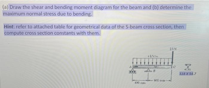
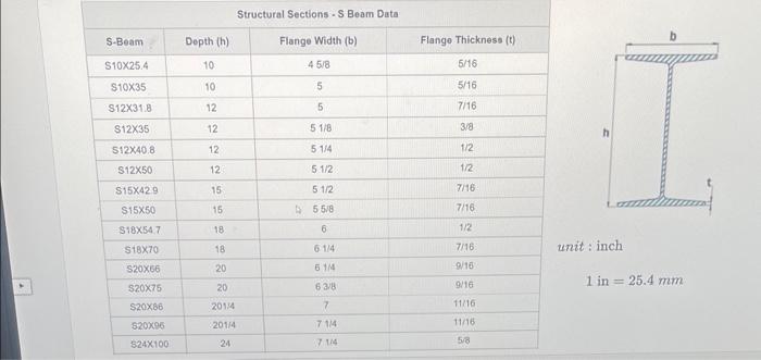
(a) Draw the shear and bending moment diagram for the beam and (b) determine the maximum normal stress due to bending. Hint: refer to attached table for geometrical data of the S-beam cross section, then compute cross section constants with them. EEE 400 4 kN/m AB 600 21.N C $18 X 54.7
S-Beam S10X25.4 $10X35 S12X31.8 $12X35 512X40.8 $12X50 $15X42.9 $15X50 S18X54.7 S18X70 S20X66 $20X75 $20X86 $20X96 $24X100 Depth (h) 10 10 12 12 12 12 15 15 18 18 20 20 2014 201/4 24 Structural Sections S Beam Data: Flange Width (b) 45/8 5 5 5 1/8 5 1/4 5.1/2 51/2 55/8 6 6 1/4 6 1/4 63/8 7 71/4 7 1/4 Flange Thickness (t) 5/16 5/16 7/16 3/8 1/2 1/2 7/16 7/16 1/2 7/16 9/16 9/16 11/16 11/16 5/8 h unit: inch 1 in = 25.4 mm
Join a community of subject matter experts. Register for FREE to view solutions, replies, and use search function. Request answer by replying!