Page 1 of 1
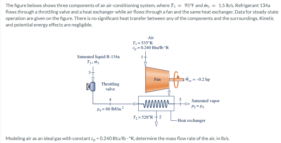
The figure belows shows three components of an air-conditioning system, where T3 = 95°F and m3 = 1.5 lb/s. Refrigerant 1
Posted: Fri Jul 01, 2022 6:17 am
by answerhappygod
- The Figure Belows Shows Three Components Of An Air Conditioning System Where T3 95 F And M3 1 5 Lb S Refrigerant 1 1 (42.08 KiB) Viewed 65 times
The figure belows shows three components of an air-conditioning system, where T3 = 95°F and m3 = 1.5 lb/s. Refrigerant 134a flows through a throttling valve and a heat exchanger while air flows through a fan and the same heat exchanger. Data for steady-state operation are given on the figure. There is no significant heat transfer between any of the components and the surroundings. Kinetic and potential energy effects are negligible. Saturated liquid R-134a T3, m3 Throttling valve 4 + P4 = 60 lbf/in.² Air T₁ = 535°R Cp = 0.240 Btu/lb.°R Fan Hik T₂=528°R +2 5 Wey = -0.2 hp www. Saturated vapor P5 = P4 -Heat exchanger Modeling air as an ideal gas with constant cp = 0.240 Btu/lb. "R, determine the mass flow rate of the air, in lb/s.