Business, Finance, Economics, Accounting, Operations Management, Computer Science, Electrical Engineering, Mechanical Engineering, Civil Engineering, Chemical Engineering, Algebra, Precalculus, Statistics and Probabilty, Advanced Math, Physics, Chemistry, Biology, Nursing, Psychology, Certifications, Tests, Prep, and more.
-
answerhappygod
- Site Admin
- Posts: 899603
- Joined: Mon Aug 02, 2021 8:13 am
Post
by answerhappygod »

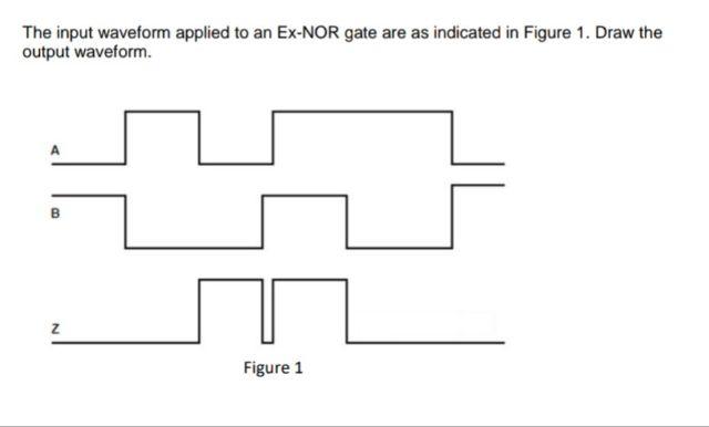
- The Input Waveform Applied To An Ex Nor Gate Are As Indicated In Figure 1 Draw The Output Waveform Z Figure 1 1 (15.44 KiB) Viewed 31 times
The input waveform applied to an Ex-NOR gate are as indicated in Figure 1. Draw the output waveform. Z Figure 1
Join a community of subject matter experts. Register for FREE to view solutions, replies, and use search function. Request answer by replying!