Page 1 of 1
The circuit diagram below shows a DC-DC converter. Assume that the inverter operates in continuous line mode (CCM), i.e.
Posted: Thu Jun 02, 2022 8:47 am
by answerhappygod
- The Circuit Diagram Below Shows A Dc Dc Converter Assume That The Inverter Operates In Continuous Line Mode Ccm I E 1 (33.71 KiB) Viewed 27 times
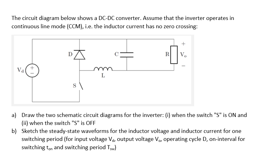
The circuit diagram below shows a DC-DC converter. Assume that the inverter operates in continuous line mode (CCM), i.e. the inductor current has no zero crossing: + R Vo Val L a) Draw the two schematic circuit diagrams for the inverter: (i) when the switch "S" is ON and (ii) when the switch "S" is OFF b) Sketch the steady-state waveforms for the inductor voltage and inductor current for one switching period (for input voltage V₁, output voltage V₁, operating cycle D, on-interval for switching ton and switching period Tsw)