(b) Sketch the root-locus diagram, including any asymptotes.
Indicate the point of instability and the positions of small
positive values of K. Comment on the nature of system damping for 0
< 𝐾 ≤ ∞. [8 marks]
(c) Derive an expression for the open-loop frequency response of
the system with respect to K for 𝜔 → 0 and 𝜔 → ∞ and hence, show a
simple Nyquist sketch of the open-loop response of the system. [6
marks]
(d) With the aid of the Routh-Hurwitz stability criterion,
investigate the range of the gain K that would guarantee the
stability of the system and hence, find the frequency of
oscillation at the marginal stability point. [8 marks]
(e) An input r(t) = 1.4u(t) is applied to the system, where the
function u(t) is the unit step function. It is desired that the
steady-state error, ess < 0.14. Determine the minimum value of K
that would satisfy the design requirement.
- B Sketch The Root Locus Diagram Including Any Asymptotes Indicate The Point Of Instability And The Positions Of Smal 1 (106.9 KiB) Viewed 30 times
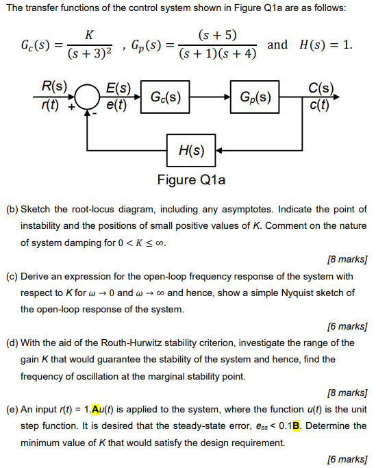
The transfer functions of the control system shown in Figure Q1a are as follows: K G(S) = (s + 3)2 (s + 5) Gp(S) = (s + 1)(s + 4) = and H(S) = 1. ! R(S). r(t) + E(S) O Gc(s) Gp(s) C(s). c(t) e(t) H(S) + Figure Q1a (b) Sketch the root-locus diagram, including any asymptotes. Indicate the point of instability and the positions of small positive values of K. Comment on the nature of system damping for 0 <KSO. [8 marks) (c) Derive an expression for the open-loop frequency response of the system with respect to K for w → 0 and w+ and hence, show a simple Nyquist sketch of the open-loop response of the system. [6 marks] (d) With the aid of the Routh-Hurwitz stability criterion, investigate the range of the gain that would guarantee the stability of the system and hence, find the frequency of oscillation at the marginal stability point. [8 marks] (e) An input r(t) = 1.Au(t) is applied to the system, where the function u(t) is the unit step function. It is desired that the steady-state error, ess < 0.13. Determine the minimum value of that would satisfy the design requirement. [6 marks)
(f) For the block diagram of a control system shown in Figure Q1b, derive the closed-loop transfer function, C(s)/R(s). [6 marks] Gr(s) D(s) R(S) E(s) C(s) Gz(s) G3(s) Hi(s) Figure Q1b