Page 1 of 1
8 52 +9.2s + 26.5 Figure 3: block diagram for open loop system Using the root locus method design your PID controller 1.
Posted: Sun May 15, 2022 4:00 pm
by answerhappygod
- 8 52 9 2s 26 5 Figure 3 Block Diagram For Open Loop System Using The Root Locus Method Design Your Pid Controller 1 1 (60 KiB) Viewed 40 times
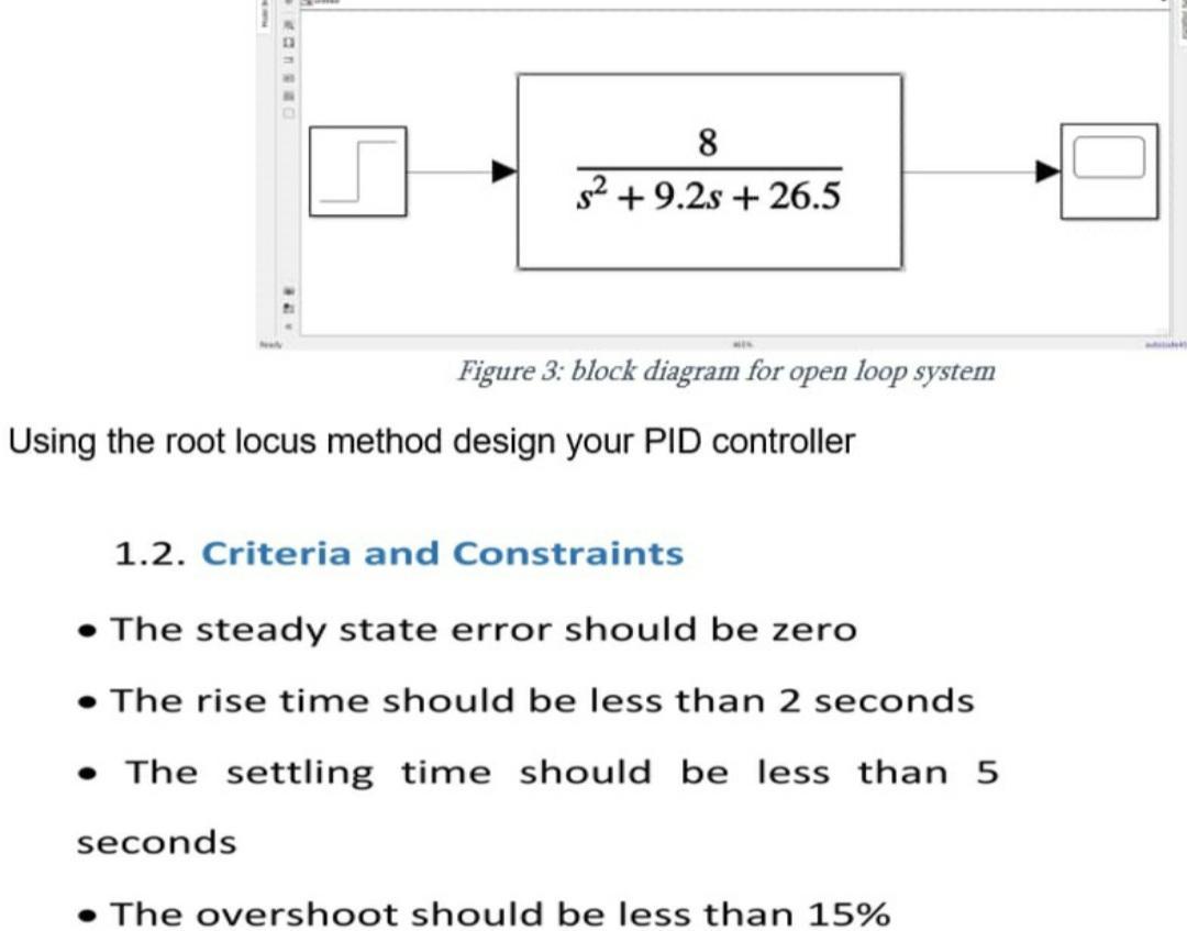
8 52 +9.2s + 26.5 Figure 3: block diagram for open loop system Using the root locus method design your PID controller 1.2. Criteria and Constraints • The steady state error should be zer • The rise time should be less than 2 seconds • The settling time should be less than 5 seconds The overshoot should be less than 15%