Page 1 of 1
The circuit in Figure 3.1 is designed such that the 50 Hz current source delivers maximum power to the load modeled by t
Posted: Thu May 05, 2022 2:15 pm
by answerhappygod
- The Circuit In Figure 3 1 Is Designed Such That The 50 Hz Current Source Delivers Maximum Power To The Load Modeled By T 1 (28.56 KiB) Viewed 37 times
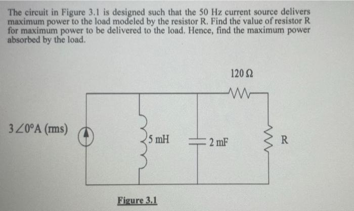
The circuit in Figure 3.1 is designed such that the 50 Hz current source delivers maximum power to the load modeled by the resistor R. Find the value of resistor R for maximum power to be delivered to the load. Hence, find the maximum power absorbed by the load. 120 Ω www 320°A (ms) 5 mH Figure 3.1 2 mF R