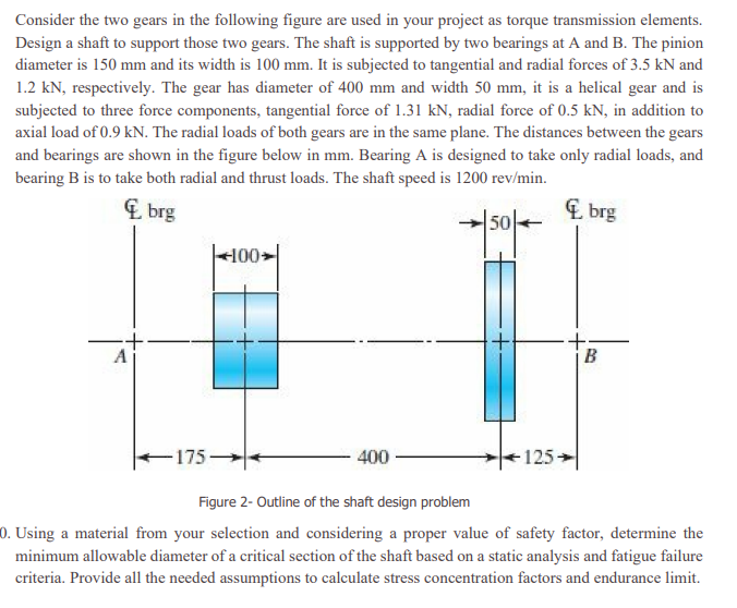
Consider the two gears in the following figure are used in your
project as torque transmission elements. Design a shaft to support
those two gears. The shaft is supported by two bearings at A and B.
The pinion diameter is 150 mm and its width is 100 mm. It is
subjected to tangential and radial forces of 3.5 kN and 1.2 kN,
respectively. The gear has diameter of 400 mm and width 50 mm, it
is a helical gear and is subjected to three force components,
tangential force of 1.31 kN, radial force of 0.5 kN, in addition to
axial load of 0.9 kN. The radial loads of both gears are in the
same plane. The distances between the gears and bearings are shown
in the figure below in mm. Bearing A is designed to take only
radial loads, and bearing B is to take both radial and thrust
loads. The shaft speed is 1200 rev/min.
10. Using a material from your selection and considering a
proper value of safety factor, determine the minimum allowable
diameter of a critical section of the shaft based on a static
analysis and fatigue failure criteria. Provide all the needed
assumptions to calculate stress concentration factors and endurance
limit.
- Consider The Two Gears In The Following Figure Are Used In Your Project As Torque Transmission Elements Design A Shaft 1 (140.53 KiB) Viewed 41 times
Consider the two gears in the following figure are used in your project as torque transmission elements. Design a shaft to support those two gears. The shaft is supported by two bearings at A and B. The pinion diameter is 150 mm and its width is 100 mm. It is subjected to tangential and radial forces of 3.5 kN and 1.2 kN, respectively. The gear has diameter of 400 mm and width 50 mm, it is a helical gear and is subjected to three force components, tangential force of 1.31 kN, radial force of 0.5 kN, in addition to axial load of 0.9 kN. The radial loads of both gears are in the same plane. The distances between the gears and bearings are shown in the figure below in mm. Bearing A is designed to take only radial loads, and bearing B is to take both radial and thrust loads. The shaft speed is 1200 rev/min. brg brg |<100 А B 175+ 400 125 - Figure 2- Outline of the shaft design problem 0. Using a material from your selection and considering a proper value of safety factor, determine the minimum allowable diameter of a critical section of the shaft based on a static analysis and fatigue failure criteria. Provide all the needed assumptions to calculate stress concentration factors and endurance limit.