System dynamics of the PWR primary system are defined by seven
differential equations (for the single precursor group
simplification). Consider the linearized form of these equations,
with seven state variables: δ P Po , δC, δTf , δθ1, δθ2, δTC L,
δTHL, and two input variables: δρex t coolant temperature going
into the steam generator? Develop a state-space model of the PWR
primary system and implement it in MATLAB-Simulink.
Use the design parameters given along with a nominal steam
generator temperature of 560.8oF. Determine if the linearized
system is stable or unstable; explain how you know.
- System Dynamics Of The Pwr Primary System Are Defined By Seven Differential Equations For The Single Precursor Group Si 1 (245.26 KiB) Viewed 59 times
Calculate the initial conditions at 100% power for each of the
seven state variables. Using the open-loop response (e.g., the
system with no controllers), determine the response of the primary
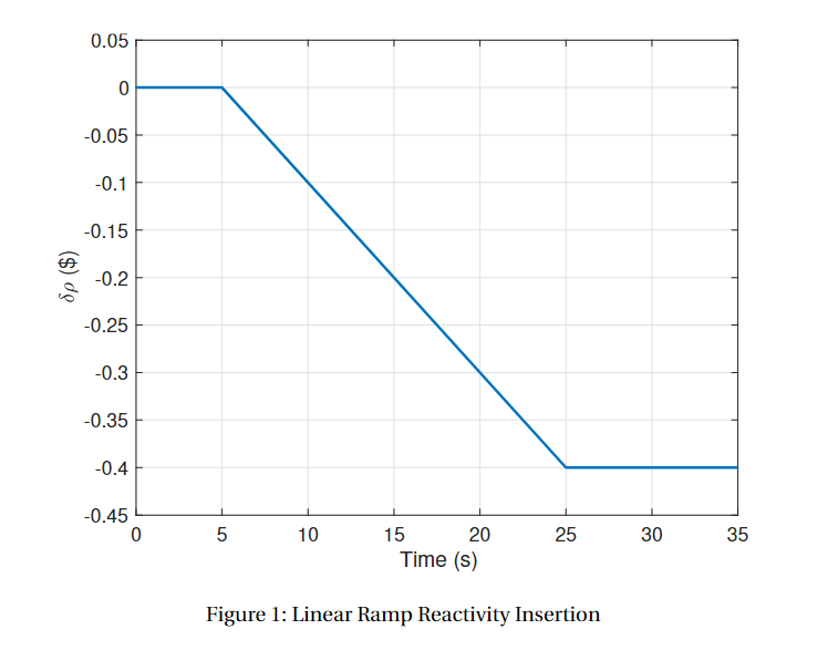
system to a perturbation in external reactivity of δρext = −40
cents inserted as a linear ramp over 20 seconds beginning at time t
= 5s (shown in Figure 1).
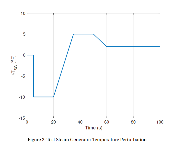
Plot all the state variables for a total simulation time of 100
seconds. Determine the open-loop response to a perturbation in the
steam generator temperature of δTSG = +10oF at time t = 5s. Plot
all the state variables for a total simulation time of 100
seconds.
- System Dynamics Of The Pwr Primary System Are Defined By Seven Differential Equations For The Single Precursor Group Si 2 (31.47 KiB) Viewed 59 times
- System Dynamics Of The Pwr Primary System Are Defined By Seven Differential Equations For The Single Precursor Group Si 3 (24.22 KiB) Viewed 59 times
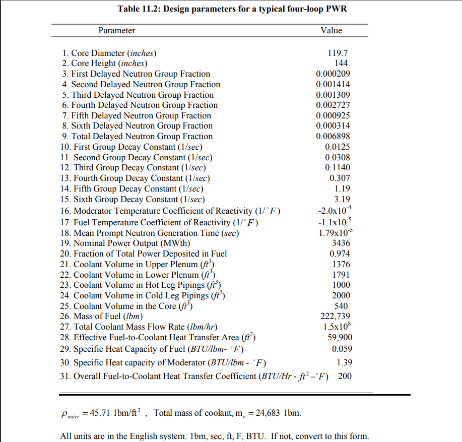
Table 11.2: Design parameters for a typical four-loop PWR Parameter Value 1. Core Diameter (inches) 119.7 2. Core Height (inches) 144 3. First Delayed Neutron Group Fraction 0.000209 4. Second Delayed Neutron Group Fraction 0.001414 5. Third Delayed Neutron Group Fraction 0.001309 6. Fourth Delayed Neutron Group Fraction 0.002727 7. Fifth Delayed Neutron Group Fraction 0.000925 8. Sixth Delayed Neutron Group Fraction 0.000314 9. Total Delayed Neutron Group Fraction 0.006898 10. First Group Decay Constant (1/sec) 0.0125 11. Second Group Decay Constant (1/sec) 0.0308 12. Third Group Decay Constant (1/sec) 0.1140 13. Fourth Group Decay Constant (1/sec) 0.307 14. Fifth Group Decay Constant (1/sec) 1.19 15. Sixth Group Decay Constant (1/sec) 3.19 16. Moderator Temperature Coefficient of Reactivity (1/°F) -2.0x10⁴ 17. Fuel Temperature Coefficient of Reactivity (1/°F) -1.1x10⁻⁵ 18. Mean Prompt Neutron Generation Time (sec) 1.79x10⁻⁵ 19. Nominal Power Output (MWh) 3436 20. Fraction of Total Power Deposited in Fuel 0.974 21. Coolant Volume in Upper Plenum (ft) 1376 22. Coolant Volume in Lower Plenum (ft'). 1791 23. Coolant Volume in Hot Leg Pipings (ft) 1000 24. Coolant Volume in Cold Leg Pipings (fr) 2000 25. Coolant Volume in the Core (ft") 26. Mass of Fuel (Ibm) 222,739 27. Total Coolant Mass Flow Rate (lbm/hr) 1.5x10⁸ 28. Effective Fuel-to-Coolant Heat Transfer Area (ft) 59,900 29. Specific Heat Capacity of Fuel (BTU/lbm- °F) 0.059 30. Specific Heat capacity of Moderator (BTU/lbm - °F) 1.39 31. Overall Fuel-to-Coolant Heat Transfer Coefficient (BTU/Hr - ft? -°F) 200 540 Pwater = 45.71 lbm/At?, Total mass of coolant, m. = 24,683 lbm. All units are in the English system: lbm, sec, ft, F, BTU. If not, convert to this form.
0.05 0 -0.05 -0.1 -0.15 ($) 09 -0.2 -0.25 -0.3 -0.35 -0.4 -0.45 0 LO 10 25 30 35 15 20 Time (s) Figure 1: Linear Ramp Reactivity Insertion
10 5 0 "sa (°F) to -5 -10 -15 0 20 40 80 100 60 Time (s) Figure 2: Test Steam Generator Temperature Perturbation