Page 1 of 1
The circuit shown below contains four capacitors and an ideal battery. C2 (12.0 uF) 5 (3.00 V) C1 (4.00 uF) C3 (6.00 uF)
Posted: Fri Apr 29, 2022 11:32 am
by answerhappygod
- The Circuit Shown Below Contains Four Capacitors And An Ideal Battery C2 12 0 Uf 5 3 00 V C1 4 00 Uf C3 6 00 Uf 1 (48.24 KiB) Viewed 43 times
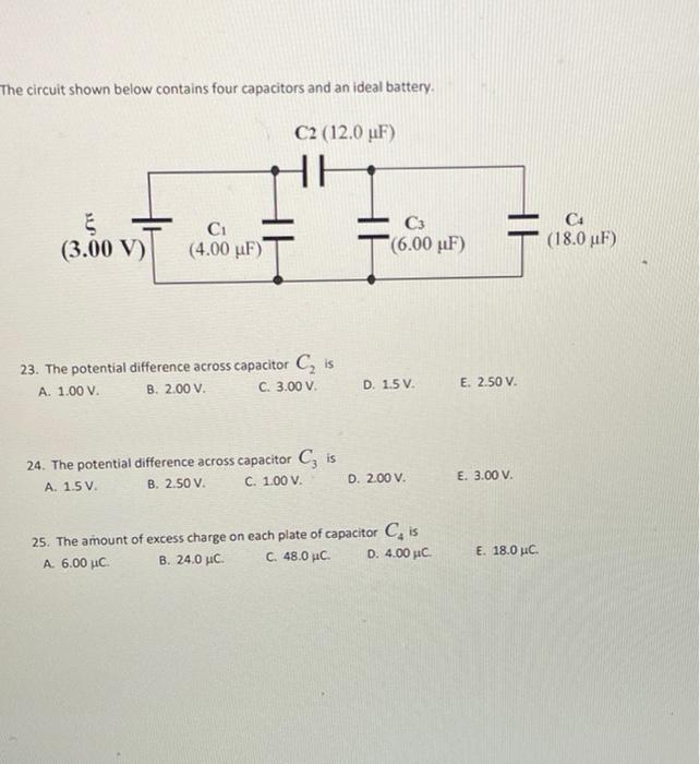
The circuit shown below contains four capacitors and an ideal battery. C2 (12.0 uF) 5 (3.00 V) C1 (4.00 uF) C3 (6.00 uF) CH (18.0 uF) I 23. The potential difference across capacitor C, is A. 1.00 V. B. 2.00 V. C. 3.00 V D. 1.5 V E. 2.50 V. 24. The potential difference across capacitor C, is A 1.5 V B. 2.50 V. C. 1.00 V. D. 2.00 V. E. 3.00 V. 25. The amount of excess charge on each plate of capacitor Cis A. 6.00 μC. Β. 24.0 μC. C. 48.0 μC. D. 4.00 C E. 18.0 uc