Page 1 of 1
Problem #B2) Design a Reduced-Voltage (Series-Resistance) Motor-Starter with Overload Protection for 13 points a 208V, 3
Posted: Fri Apr 29, 2022 11:02 am
by answerhappygod
- Problem B2 Design A Reduced Voltage Series Resistance Motor Starter With Overload Protection For 13 Points A 208v 3 1 (148.42 KiB) Viewed 37 times
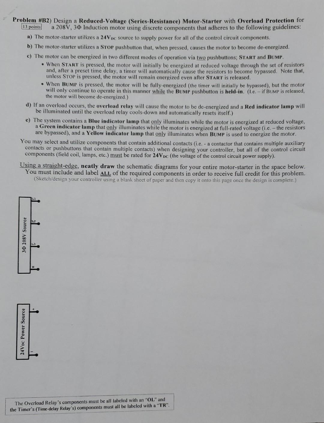
Problem #B2) Design a Reduced-Voltage (Series-Resistance) Motor-Starter with Overload Protection for 13 points a 208V, 30 Induction motor using discrete components that adheres to the following guidelines: a) The motor-starter utilizes a 24Vpc source to supply power for all of the control circuit components. b) The motor-starter utilizes a Stop pushbutton that, when pressed, causes the motor to become de-energized. c) The motor can be energized in two different modes of operation via two pushbuttons, START and BUMP. • When START is pressed the motor will initially be energized at reduced voltage through the set of resistors and, after a preset time delay, a timer will automatically cause the resistors to become bypassed. Note that, unless STOP is pressed, the motor will remain energized even after START is released. • When Bump is pressed, the motor will be fully-energized the timer will initially be bypassed), but the motor will only continue to operate in this manner while the Bump pushbutton is held-in. (1.c. - if BUMP is released, the motor will become de-energized.) d) If an overload occurs, the overload relay will cause the motor to be de-energized and a Red indicator lamp will be illuminated until the overload relay cools-down and automatically resets itself.) e) The system contains a Blue indicator lamp that only illuminates while the motor is energized at reduced voltage, a Green indicator lamp that only illuminates while the motor is energized at full-rated voltage (i.e. - the resistors are bypassed), and a Yellow indicator lamp that only illuminates when BUMP is used to energize the motor. You may select and utilize components that contain additional contacts (i.e. - a contactor that contains multiple auxiliary contacts or pushbuttons that contain multiple contacts) when designing your controller, but all of the control circuit components (field coil, lamps, etc.) must be rated for 24Vpc (the voltage of the control circuit power supply). Using a straight-edge, neatly draw the schematic diagrams for your entire motor-starter in the space below. You must include and label ALL of the required components in order to receive full credit for this problem. (Sketch/design your controller using a blank sheet of paper and then copy it onto this page once the design is complete.) 30 208V Source 24VDC Power Source I The Overload Relay's components must be all labeled with an "OL" and the Timer's (Time-delay Relay's) components must all be labeled with a "TR".