Page 1 of 1
Question 1 In this test, you will be designing a simple Traffic Light System as shown in Figure 1. In this system, there
Posted: Fri Apr 29, 2022 10:50 am
by answerhappygod
- Question 1 In This Test You Will Be Designing A Simple Traffic Light System As Shown In Figure 1 In This System There 1 (76.85 KiB) Viewed 30 times
- Question 1 In This Test You Will Be Designing A Simple Traffic Light System As Shown In Figure 1 In This System There 2 (53.97 KiB) Viewed 30 times
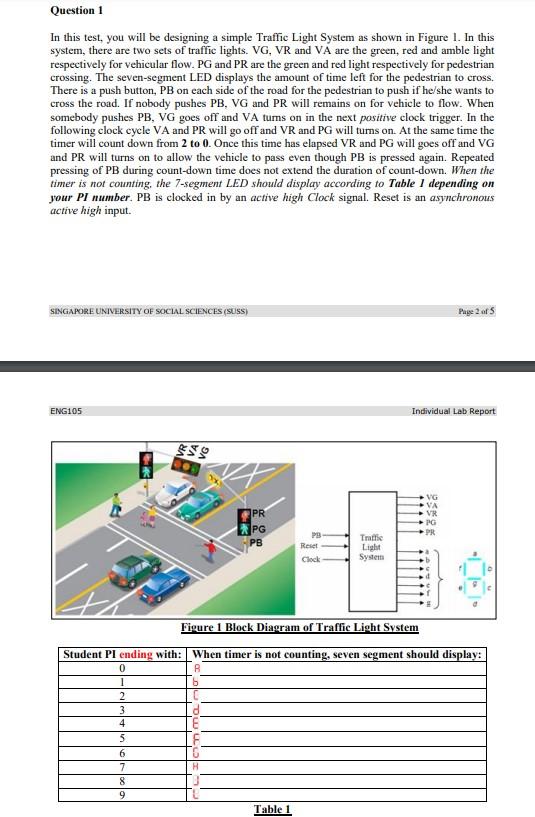
Question 1 In this test, you will be designing a simple Traffic Light System as shown in Figure 1. In this system, there are two sets of traffic lights. VG, VR and VA are the green, red and amble light respectively for vehicular flow.PG and PR are the green and red light respectively for pedestrian crossing. The seven-segment LED displays the amount of time left for the pedestrian to cross. There is a push button, PB on each side of the road for the pedestrian to push if he/she wants to cross the road. If nobody pushes PB, VG and PR will remains on for vehicle to flow. When somebody pushes PB, VG goes off and VA tums on in the next positive clock trigger. In the following clock cycle VA and PR will go off and VR and PG will tums on. At the same time the timer will count down from 2 to 0. Once this time has elapsed VR and PG will goes off and VG and PR will turns on to allow the vehicle to pass even though PB is pressed again. Repeated pressing of PB during count-down time does not extend the duration of count-down. When the timer is not counting, the 7-segment LED should display according to Table 1 depending on your PI number. PB is clocked in by an active high Clock signal. Reset is an asynchronous active high input. SINGAPORE UNIVERSITY OF SOCIAL SCIENCES (SUSS) Page 2 of 5 ENG105 Individual Lab Report VG VA VR PG PR X PG PB PB Reset Clock Traffic Light System Figure 1 Block Diagram of Traffic Light System Student PI ending with: When timer is not counting, seven segment should display: 0 1 2 3 4 5 6 7 8 9 Table 1 onimian -
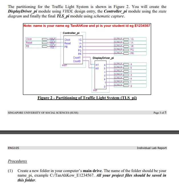
The partitioning for the Traffic Light System is shown in Figure 2. You will create the Display Driver_pi module using VHDL design entry, the Controller_pi module using the state diagram and finally the final TLS_pi module using schematic capture. Note: name is your name eg TanAhKow and pi is your student id eg E1234567 Controller_pi Clock Reset PB Clock Reset PB VG VA VR PG PR Count: Counto QUIRED VG OUTLET VA QUIAL DVR BULO PG QURULO PR Display Driver_pi a insi E in1 ind a b C DUTULO CUTE LO e 1 OUTLO GUILLO 9 inst Figure 2 - Partitioning of Traffic Light System (TLS pi) SINGAPORE UNIVERSITY OF SOCIAL SCIENCES (SUSS) Page 3 of 5 ENG105 Individual Lab Report Procedures (1) Create a new folder in your computer's main drive. The name of the folder should be your name pi, example C:/TanAhKow_E1234567. All your project files should be saved in this folder.