Page 1 of 1
Figure Q2 illustrates the connection of a cylinder head (Aluminum alloy, E = 72GPa) to an pressure vessel (Aluminum, all
Posted: Fri Apr 29, 2022 10:13 am
by answerhappygod
- Figure Q2 Illustrates The Connection Of A Cylinder Head Aluminum Alloy E 72gpa To An Pressure Vessel Aluminum All 1 (54.08 KiB) Viewed 31 times
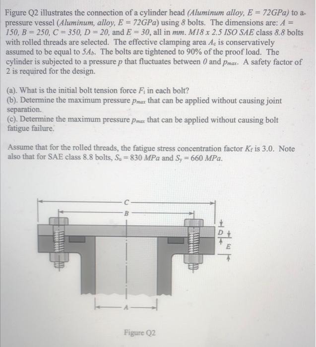
Figure Q2 illustrates the connection of a cylinder head (Aluminum alloy, E = 72GPa) to an pressure vessel (Aluminum, alloy, E = 72GPa) using 8 bolts. The dimensions are: A 150, B = 250, C = 350, D = 20, and E = 30, all in mm. M18 x 2.5 ISO SAE class 8.8 bolts with rolled threads are selected. The effective clamping area Ac is conservatively assumed to be equal to 5A). The bolts are tightened to 90% of the proof load. The cylinder is subjected to a pressure p that fluctuates between 0 and Pmar. A safety factor of 2 is required for the design. (a). What is the initial bolt tension force Fi in each bolt? (b). Determine the maximum pressure Pmax that can be applied without causing joint separation. (c). Determine the maximum pressure Pmax that can be applied without causing bolt fatigue failure. Assume that for the rolled threads, the fatigue stress concentration factor Kris 3.0. Note also that for SAE class 8.8 bolts, Su = 830 MPa and Sy = 660 MPa. D Figure Q2