Page 1 of 1
The resistors in the operational amplifier circuit shown Figure 1.1 are Ry = 8 k1, R2 = 8 kN, R3 = 2 k., and R4 = 4 k. T
Posted: Fri Apr 29, 2022 9:51 am
by answerhappygod
- The Resistors In The Operational Amplifier Circuit Shown Figure 1 1 Are Ry 8 K1 R2 8 Kn R3 2 K And R4 4 K T 1 (31.03 KiB) Viewed 14 times
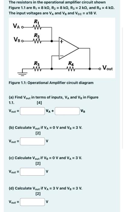
The resistors in the operational amplifier circuit shown Figure 1.1 are Ry = 8 k1, R2 = 8 kN, R3 = 2 k., and R4 = 4 k. The input voltages are VA and Vg and Vcc = +18 V. R1 Vaa R2 VBO w R3 RA wi Vout Figure 1.1: Operational Amplifier circuit diagram (a) Find Vout in terms of inputs, VA and Vg in Figure [4] Vout = VA+ VE 1.1. (b) Calculate Vout if VA = 0 V and Vg = 3 V. [2] Vout v (c) Calculate Vout if V3 = 0 V and VA = 3 V. [2] Vout = (d) Calculate Vout if VA= 3 V and Vg = 3 V. [2] Vout V