Page 1 of 1
4. The MOS amplifier shown in Figure 4 is identical to that of in Figure 3, except for the following: Real capacitors ar
Posted: Fri Apr 29, 2022 9:09 am
by answerhappygod
- 4 The Mos Amplifier Shown In Figure 4 Is Identical To That Of In Figure 3 Except For The Following Real Capacitors Ar 1 (76.43 KiB) Viewed 26 times
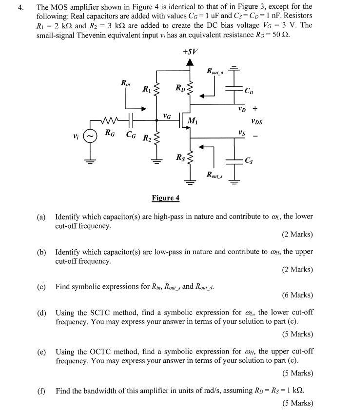
4. The MOS amplifier shown in Figure 4 is identical to that of in Figure 3, except for the following: Real capacitors are added with values CG= 1 uF and Cs=CD = 1 nF. Resistors R1 = 2 k12 and R2 = 3 k12 are added to create the DC bias voltage Vo = 3 V. The small-signal Thevenin equivalent input v; has an equivalent resistance RG = 50 12. +5V Routd Rin R1 } RD CD VD + VG WH M VDS RG Vi Co R2 Vs Rs Cs Routs Figure 4 (a) Identify which capacitor(s) are high-pass in nature and contribute to ol, the lower cut-off frequency. (2 Marks) (b) Identify which capacitor(s) are low-pass in nature and contribute to on, the upper cut-off frequency (2 Marks) (c) Find symbolic expressions for Rin, Rou_s and Rout_d. (6 Marks) (d) Using the SCTC method, find a symbolic expression for @l, the lower cut-off frequency. You may express your answer in terms of your solution to part (c). (5 Marks) (e) Using the OCTC method, find a symbolic expression for Oh, the upper cut-off frequency. You may express your answer in terms of your solution to part (c). (5 Marks) (1) Find the bandwidth of this amplifier in units of rad/s, assuming Rp = Rs = 1 kN. (5 Marks)