Page 1 of 1
1. (a) A non-ideal Op-Amp circuit configured with 2 Op-Amps, 2 diodes and 6 resistors is shown in Figure 1 on page 2. Th
Posted: Fri Apr 29, 2022 9:09 am
by answerhappygod
- 1 A A Non Ideal Op Amp Circuit Configured With 2 Op Amps 2 Diodes And 6 Resistors Is Shown In Figure 1 On Page 2 Th 1 (49.95 KiB) Viewed 22 times
- 1 A A Non Ideal Op Amp Circuit Configured With 2 Op Amps 2 Diodes And 6 Resistors Is Shown In Figure 1 On Page 2 Th 2 (24.48 KiB) Viewed 22 times
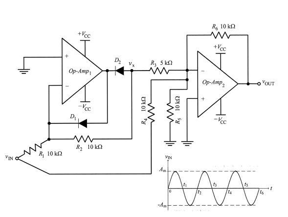
1. (a) A non-ideal Op-Amp circuit configured with 2 Op-Amps, 2 diodes and 6 resistors is shown in Figure 1 on page 2. The Op-Amps are powered by + Vcc of #15 V power supplies. It has 1 AC input voltage source, VIN and the Op-Amps are non-ideal owing to their slew rate (SR) limitation of 1 V/uS and the unity gain bandwidth of 1 MHz. The input voltage source of vin can be written as Amsinot or Amsin2nfi. Given that R1 = R2 = R4 = Rs = R6 = 10 k2, R3 = 5 k2 and Am = 1 V. (1) Sketch the waveforms Vx, VOUT|wx (vout with input from vx through R3), VOUTIWIN (VOUT with input from vin through R4 only) and vout (by superposition) with reference to the input sinewave Vin as shown at the bottom right-hand corner of Figure 1 (shown in terms of Am and 11...16). (ii) Find the maximum frequency in hertz that the input voltage can have before slew rate limitation occurs. (15 Marks) Note: Question No. 1 continues on page 2. 1
R, 10 kΩ +Vcc w +Voc D2 Ryska W Op-Amp Op-Amp 2 YOUT -PC R4 10k2 Rς 10 kΩ D R, 10 kΩ VIN R, 10k2 VIN Am ANA 1 14 16 -Am