Page 1 of 1
(2) Write VHDL code to implement the Display Driver_pi module. When the timer is not counting, the seven segment display
Posted: Fri Apr 29, 2022 8:49 am
by answerhappygod
- 2 Write Vhdl Code To Implement The Display Driver Pi Module When The Timer Is Not Counting The Seven Segment Display 1 (115.46 KiB) Viewed 59 times
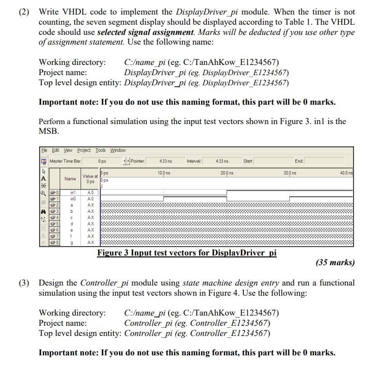
(2) Write VHDL code to implement the Display Driver_pi module. When the timer is not counting, the seven segment display should be displayed according to Table 1. The VHDL code should use selected signal assignment. Marks will be deducted if you use other type of assignment statement. Use the following name: Working directory: C:/name pi (eg. C:/TanAhKow_E1234567) Project name: Display Driver_pi (eg. Display Driver_E1234567) Top level design entity: Display Driver_pi (eg. DisplayDriver_E1234567) Important note: If you do not use this naming format, this part will be 0 marks. Perform a functional simulation using the input test vectors shown in Figure 3. inl is the MSB. 4.33ns Interval 433 ns Start End Ele Edt Vew Project Tools Window Master Time Bar Ops .. Pointer pps Оря 10.00 20.0 ns 30 Ons 40. Ons Name Value at Ops <<XE DO in 1 in 2 an b ce | | | | | АО AD AX AX AX AX AX AX 了了了了 C 06 7 8 d e 1 9 AX Figure 3 Input test vectors for Display Driver pi (35 marks) (3) Design the Controller_pi module using state machine design entry and run a functional simulation using the input test vectors shown in Figure 4. Use the following: Working directory: C:/name_pi (eg. C:/TanAhKow_E1234567) Project name: Controller pi (eg. Controller_E1234567) Top level design entity: Controller pi (eg. Controller E1234567) Important note: If you do not use this naming format, this part will be 0 marks.