Page 1 of 1
2. (6 Marks) The block diagram of the rate loop for a missile autopilot is shown in Figure 2. The command input is r(t)
Posted: Fri Apr 29, 2022 8:44 am
by answerhappygod
- 2 6 Marks The Block Diagram Of The Rate Loop For A Missile Autopilot Is Shown In Figure 2 The Command Input Is R T 1 (54.34 KiB) Viewed 29 times
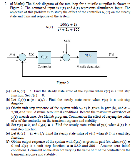
2. (6 Marks) The block diagram of the rate loop for a missile autopilot is shown in Figure 2. The command input is r(t) and d(t) represents disturbance input. The objective of this problem is to study the effect of the controller Ge(s) on the steady state and transient response of the system. 100(s + 1) G(s) = 52 + 25 + 100 D(S) R(S) E(3) G(s) YS) G (5) Controller Missile dynamics Figure 2 (a) Let Gc(s) = 1. Find the steady state error of the system when r(t) is a unit step function. Set d(t) = 0. 6) Let Ge(s) = (s + a)/s. Find the steady state error when r(t) is a unit-step function (©) Obtain unit step response of the system with Ge(s) is given in part 6), and a = 3,30, and 300. Assume zero initial conditions. Record the maximum overshoot of y(t) in each case. Use Matlab program. Comment on the effect of varying the value of a of the controller on the transient response and stability. (d) Set r(t) = 0, and Ge(9) = 1. Find the steady state value of y(t) when d(t) is a unit step function (e) Let Ge(s) = (s + a)/s. Find the steady state value of y(t) when d(t) is a unit step function. (1) Obtain output response of the system with Ge(s) as given in part (e), when r(t) = O and d(t) is a unit step fiunction; a = 3,30, and 300. Assume zero initial conditions. Comment on the effect of varying the value of a of the controller on the transient response and stability.