Page 1 of 1
The resistors in the operational amplifier circuit shown Figure 1.1 are R1 = 7 k12, R2 = 7 k, R3 = 1 ks, and R4 = 2 k. T
Posted: Fri Apr 29, 2022 8:34 am
by answerhappygod
- The Resistors In The Operational Amplifier Circuit Shown Figure 1 1 Are R1 7 K12 R2 7 K R3 1 Ks And R4 2 K T 1 (35.64 KiB) Viewed 20 times
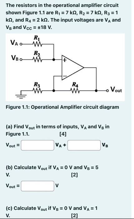
The resistors in the operational amplifier circuit shown Figure 1.1 are R1 = 7 k12, R2 = 7 k, R3 = 1 ks, and R4 = 2 k. The input voltages are VA and VB and Vcc = +18 V. Ri VAO R2 M M VBO R3 M R4 W Vout Figure 1.1: Operational Amplifier circuit diagram (a) Find Vout in terms of inputs, VA and Vg in Figure 1.1. [4] Vout = VA+ VB (b) Calculate Vout if VA = 0 V and V8 = 5 V. [2] Vout = v (c) Calculate Vout if V8 = 0 V and VA = 1 V. [2]