Page 1 of 1
(b) For the circuit shown in Figure 4b, the transistor is biased with a constant source lo=1 mA. The transistor paramete
Posted: Fri Apr 29, 2022 8:31 am
by answerhappygod
- B For The Circuit Shown In Figure 4b The Transistor Is Biased With A Constant Source Lo 1 Ma The Transistor Paramete 1 (46.2 KiB) Viewed 21 times
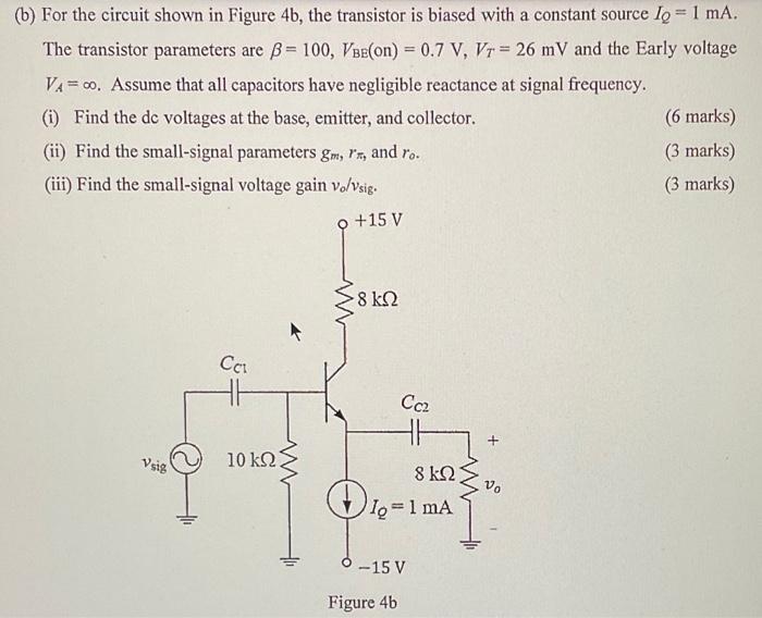
(b) For the circuit shown in Figure 4b, the transistor is biased with a constant source lo=1 mA. The transistor parameters are B = 100, VBe(on) = 0.7 V, Vr = 26 mV and the Early voltage VA= 00. Assume that all capacitors have negligible reactance at signal frequency. (1) Find the de voltages at the base, emitter, and collector. (6 marks) (ii) Find the small-signal parameters gm, rx, (3 marks) (iii) Find the small-signal voltage gain vo/Vsig. (3 marks) and ro. +15 V W 8k2 Cct HE Cc2 + Vsig 10 k92 8 k92 Vo 1.-1 mA Quia -15 V Figure 4b