Page 1 of 1
The circuit shown below contains four capacitors and an ideal battery. C2 (12.0 uF) (3.00 V) C1 (4.00 uF) C3 (6.00 uF) C
Posted: Thu Apr 28, 2022 9:46 am
by answerhappygod
- The Circuit Shown Below Contains Four Capacitors And An Ideal Battery C2 12 0 Uf 3 00 V C1 4 00 Uf C3 6 00 Uf C 1 (75.85 KiB) Viewed 48 times
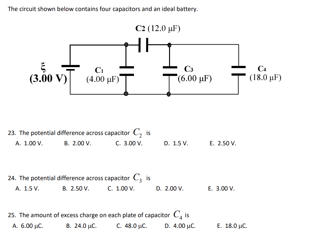
The circuit shown below contains four capacitors and an ideal battery. C2 (12.0 uF) (3.00 V) C1 (4.00 uF) C3 (6.00 uF) C4 (18.0 °F) 23. The potential difference across capacitor C2 is A. 1.00 V. B. 2.00 V. C. 3.00 V. D. 1.5 V. E. 2.50 V. 24. The potential difference across capacitor Cz is A. 1.5 V. B. 2.50 V. C. 1.00 V. D. 2.00 V. E. 3.00 V. 25. The amount of excess charge on each plate of capacitor Cdis A. 6.00 μC. Β. 24.0 μC. C. 48.0 μC. D. 4.00 uc. 4 Ε. 18.0 μC.