Page 1 of 1
Part A The lower end of the thin uniform rod in (Figure 1) is attached to the floor by a frictionless hinge at point P.
Posted: Thu Apr 28, 2022 9:03 am
by answerhappygod
- Part A The Lower End Of The Thin Uniform Rod In Figure 1 Is Attached To The Floor By A Frictionless Hinge At Point P 1 (87.53 KiB) Viewed 29 times
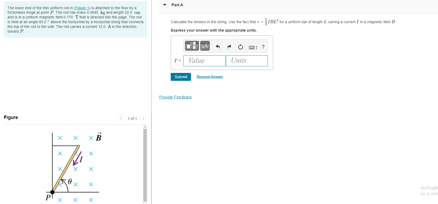
Part A The lower end of the thin uniform rod in (Figure 1) is attached to the floor by a frictionless hinge at point P. The rod has mass 0.0840 kg and length 22.0 cm and is in a uniform magnetic field 0.170 T that is directed into the page. The rod is held at an angle 60.0° above the horizontal by a horizontal string that connects the top of the rod to the wall. The rod carries a current 12.0 A in the direction toward P. Calculate the tension in the string. Use the fact that t ={IBL for a uniform bar of length L carring a current I in a magnetic field B. Express your answer with the appropriate units. Ti HA ? T = Value Units Submit Request Answer Provide Feedback Figure 1 of 1 Х х x В x Х Х Х Activate Go to Sett X X X