Page 1 of 1
2. GIVEN The link is fixed at the two ends with pins (not shown, pin holes shown instead) and is loaded with a uniform l
Posted: Wed Apr 27, 2022 7:33 pm
by answerhappygod
- 2 Given The Link Is Fixed At The Two Ends With Pins Not Shown Pin Holes Shown Instead And Is Loaded With A Uniform L 1 (130.23 KiB) Viewed 46 times
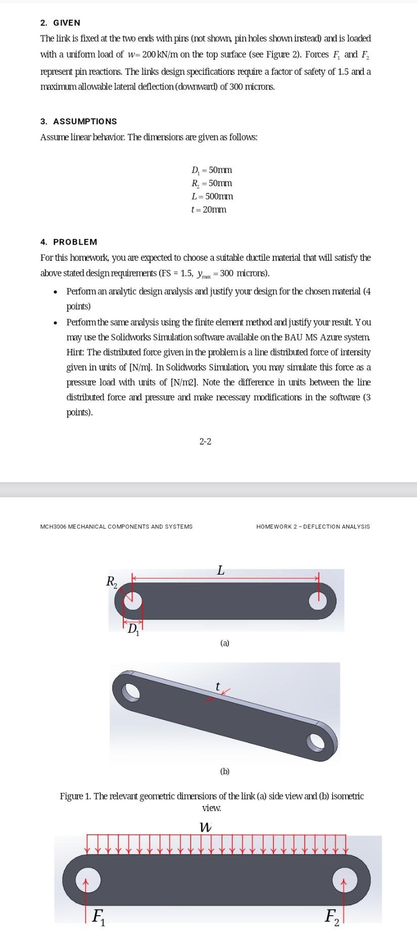
2. GIVEN The link is fixed at the two ends with pins (not shown, pin holes shown instead) and is loaded with a uniform load of w=200 kN/m on the top surface (see Figure 2). Forces F, and F, represent pin reactions. The links design specifications require a factor of safety of 1.5 and a maximum allowable lateral deflection (downward) of 300 microns. 3. ASSUMPTIONS Assume linear behavior. The dimensions are given as follows: D. = 50mm R = 50mm L = 500mm t=20mm 4. PROBLEM . . For this homework, you are expected to choose a suitable ductile material that will satisfy the above stated design requirements (FS = 1.5, yme = 300 microns). Perform an analytic design analysis and justify your design for the chosen material (4 points) Perform the same analysis using the finite element method and justify your result. You may use the Solidworks Simulation software available on the BAU MS Azure system Hint: The distributed force given in the problem is a line distributed force of intensity given in units of [N/m]. In Solidworks Simulation, you may simulate this force as a pressure load with units of [N/m2]. Note the difference in units between the line distributed force and pressure and make necessary modifications in the software (3 points). 2-2 MCH3006 MECHANICAL COMPONENTS AND SYSTEMS HOMEWORK 2-DEFLECTION ANALYSIS L R (a) (b) Figure 1. The relevant geometric dimensions of the link (a) side view and (b) isometric view. W F F 2