Page 1 of 1
For the circuit shown with the output voltage defined on the capacitor C2: R1 1kΩ ww x(t) ci 500 UF C2 500 uF y(t) Y(S)
Posted: Wed Apr 27, 2022 6:21 pm
by answerhappygod
- 1 (106.9 KiB) Viewed 33 times
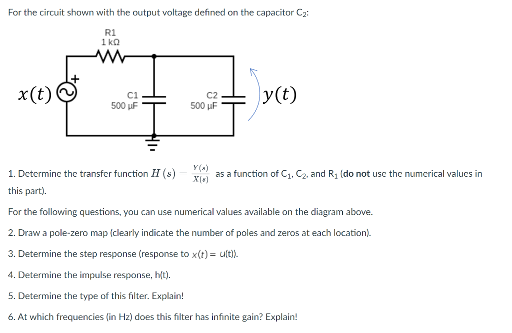
For the circuit shown with the output voltage defined on the capacitor C2: R1 1kΩ ww x(t) ci 500 UF C2 500 uF y(t) Y(S) X(8) 1. Determine the transfer function H (s) this part). as a function of C1, C2, and R1 (do not use the numerical values in For the following questions, you can use numerical values available on the diagram above. 2. Draw a pole-zero map (clearly indicate the number of poles and zeros at each location). 3. Determine the step response (response to x(t)= u(t)). 4. Determine the impulse response, h(t). 5. Determine the type of this filter. Explain! 6. At which frequencies (in Hz) does this filter has infinite gain? Explain!