Page 1 of 1
The circuit Figure Q3B shows a relaxation oscillator. с Rc V. OV •Von OV w V w R Figure Q3B Page 9 of 12 - Describe the
Posted: Wed Apr 27, 2022 5:59 pm
by answerhappygod
- 1 (56.22 KiB) Viewed 17 times
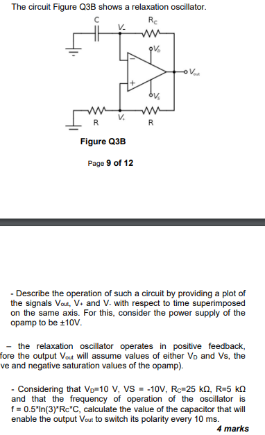
The circuit Figure Q3B shows a relaxation oscillator. с Rc V. OV •Von OV w V w R Figure Q3B Page 9 of 12 - Describe the operation of such a circuit by providing a plot of the signals Vout, V. and V- with respect to time superimposed on the same axis. For this, consider the power supply of the opamp to be +10v. the relaxation oscillator operates in positive feedback, fore the output Vout will assume values of either Vo and Vs, the ve and negative saturation values of the opamp). - Considering that Vo=10 V, VS = -10V, Rc=25 kA, R=5 ko and that the frequency of operation of the oscillator is f = 0.5*In(3)*Rc*C, calculate the value of the capacitor that will enable the output Vout to switch its polarity every 10 ms. 4 marks