Page 1 of 1
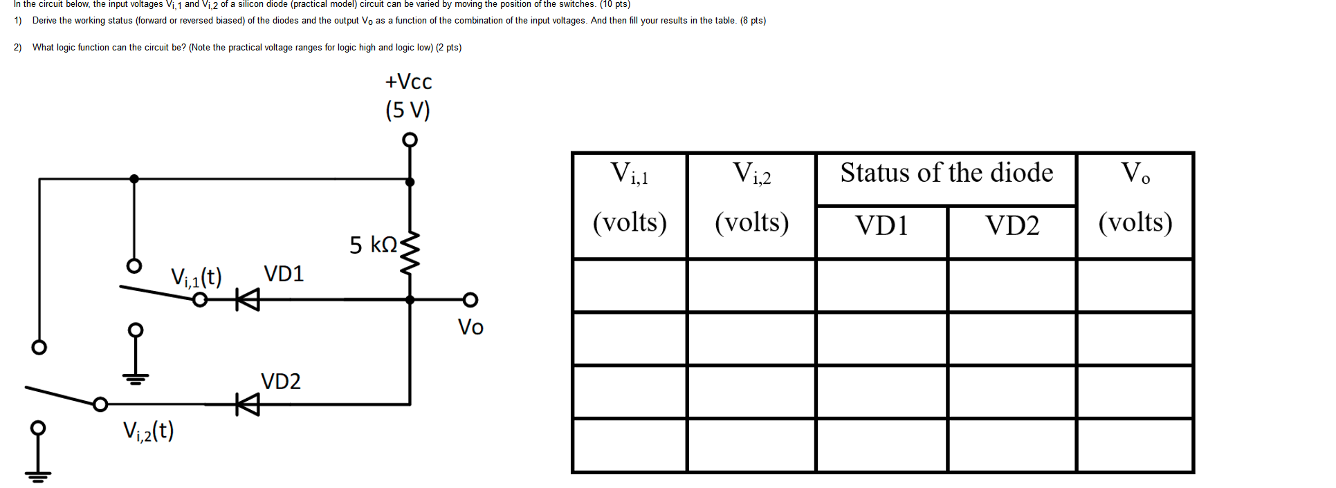
In the circuit below, the input voltages Vi, 1 and Vi, 2 of a silicon diode (practical model circuit can be varied by mo
Posted: Wed Apr 27, 2022 5:52 pm
by answerhappygod
- In The Circuit Below The Input Voltages Vi 1 And Vi 2 Of A Silicon Diode Practical Model Circuit Can Be Varied By Mo 1 (90.27 KiB) Viewed 32 times
In the circuit below, the input voltages Vi, 1 and Vi, 2 of a silicon diode (practical model circuit can be varied by moving the position of the switches. (10 pts) 1) Derive the working status (forward or reversed biased) of the diodes and the output Vo as a function of the combination of the input voltages. And then fill your results in the table. (8 pts) 2) What logic function can the circuit be? (Note the practical voltage ranges for logic high and logic low) (2 pts) +Vcc (5 V) Vil Viz Status of the diode V. (volts) (volts) VD1 VD2 (volts) 5 k2 VD1 Vil(t) O * Vo ? VD2 * Viz(t)