Page 1 of 1
Consider the circuit shown in Figure 1 below. It consists of a generator with internal resistance Ro = 50 2 that produce
Posted: Wed Apr 27, 2022 5:52 pm
by answerhappygod
- Consider The Circuit Shown In Figure 1 Below It Consists Of A Generator With Internal Resistance Ro 50 2 That Produce 1 (83.68 KiB) Viewed 29 times
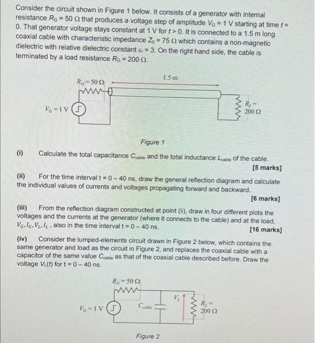
Consider the circuit shown in Figure 1 below. It consists of a generator with internal resistance Ro = 50 2 that produces a voltage step of amplitude Vo = 1 V starting at time t= 0. That generator voltage stays constant at 1 V fort > 0. It is connected to a 1.5 m long coaxial cable with characteristic impedance Z = 75 which contains a non-magnetic dielectric with relative dielectric constant & = 3. On the right hand side, the cable is terminated by a load resistance Ro = 2002 1.5 m Ra 502 WO R Vo=11s 200 12 Figure 1 (1) Calculate the total capacitance Cable and the total inductance Lcable of the cable. [5 marks] (ii) For the time interval t = 0 - 40 ns, draw the general reflection diagram and calculate the individual values of currents and voltages propagating forward and backward. [6 marks] (iii) From the reflection diagram constructed at point (1) draw in four different plots the voltages and the currents at the generator (where it connects to the cable) and at the load, Vol. VI. also in the time interval t = 0 - 40 ns. [16 marks] Consider the lumped-elements circuit drawn in Figure 2 below, which contains the same generator and load as the circuit in Figure 2, and replaces the coaxial cable with a capacitor of the same value Cable as that of the coaxial cable described before. Draw the voltage V.(t) fort = 0 - 40 ns. (iv) RG-502 VG-IV Cluble "T RE 2002 Figure 2