Page 1 of 1
Chip 74161 often can be configurated as below (on the left) to function as a counter, and the truth table is provided be
Posted: Wed Apr 27, 2022 5:13 pm
by answerhappygod
- Chip 74161 Often Can Be Configurated As Below On The Left To Function As A Counter And The Truth Table Is Provided Be 1 (90.74 KiB) Viewed 46 times
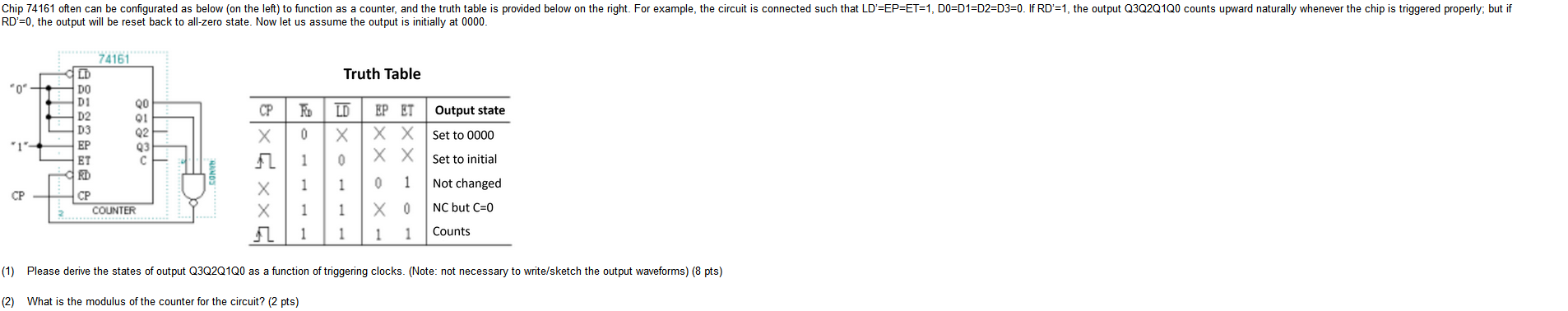
Chip 74161 often can be configurated as below (on the left) to function as a counter, and the truth table is provided below on the right. For example, the circuit is connected such that LD'=EP=ET=1, DO=D1=D2=D3=0. If RD'=1, the output Q3Q2Q1Q0 counts upward naturally whenever the chip is triggered properly; but if RD'=0, the output will be reset back to all-zero state. Now let us assume the output is initially at 0000. Truth Table "0" CP 74161 LD DO D1 QO D2 01 D3 Q2 Q3 ET С RD CP COUNTER RO 0 LD X Х "1"- EP 1 0 EP ET Output state X X Set to 0000 X X Set to initial Х 0 1 Not changed Xo NC but C=0 1 1 Counts 1 1 CP Х X 2 1 1 1 1 (1) Please derive the states of output Q3Q2Q1Q0 as a function of triggering clocks. (Note: not necessary to write/sketch the output waveforms) (8 pts) (2) What is the modulus of the counter for the circuit? (2 pts)