Page 1 of 1
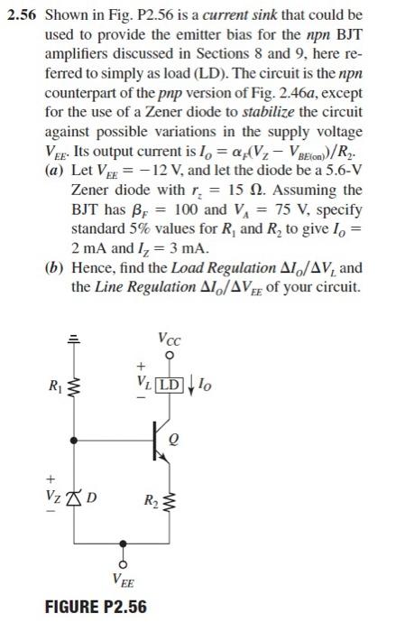
2.56 Shown in Fig. P2.56 is a current sink that could be used to provide the emitter bias for the npn BJT amplifiers dis
Posted: Wed Apr 27, 2022 5:10 pm
by answerhappygod
- 2 56 Shown In Fig P2 56 Is A Current Sink That Could Be Used To Provide The Emitter Bias For The Npn Bjt Amplifiers Dis 1 (43.17 KiB) Viewed 23 times
- 2 56 Shown In Fig P2 56 Is A Current Sink That Could Be Used To Provide The Emitter Bias For The Npn Bjt Amplifiers Dis 2 (22.92 KiB) Viewed 23 times
2.56 Shown in Fig. P2.56 is a current sink that could be used to provide the emitter bias for the npn BJT amplifiers discussed in Sections 8 and 9, here re- ferred to simply as load (LD). The circuit is the non counterpart of the pnp version of Fig. 2.46a, except for the use of a Zener diode to stabilize the circuit against possible variations in the supply voltage Ver. Its output current is 1, = a.V. - VBEion)/R. (a) Let V = -12 V, and let the diode be a 5.6-V Zener diode with r, = 15 1. Assuming the BJT has B= 100 and VA = 75 V, specify standard 5% values for R, and R, to give lo = 2 mA and I2 = 3 mA. (6) Hence, find the Load Regulation A1/AV, and the Line Regulation A1/AVof your circuit. = Voc R3 VILD 110 the Q + VZD R2 VEE FIGURE P2.56
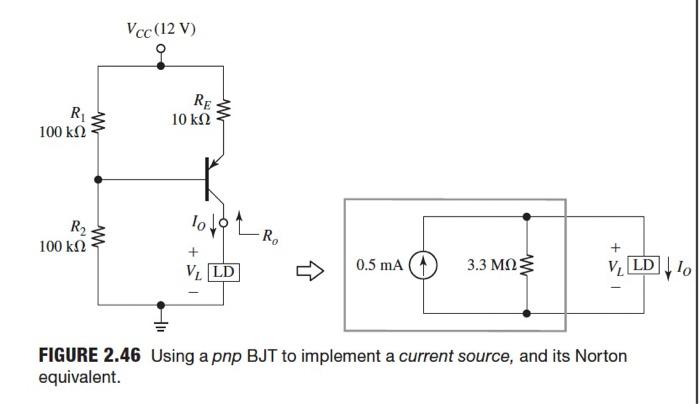
Vcc (12V) R 100 k12 W RE 10 k12 R2 10 10 w RO 100 k12 3.3 ΜΩ: V. LD 0.5 mA V. LD 10 FIGURE 2.46 Using a pnp BJT to implement a current source, and its Norton equivalent.