Page 1 of 1
A silicon-based NPN BJT is connected as shown below on the left, and its DC load line is shown on the right. Assuming th
Posted: Wed Apr 27, 2022 5:09 pm
by answerhappygod
- A Silicon Based Npn Bjt Is Connected As Shown Below On The Left And Its Dc Load Line Is Shown On The Right Assuming Th 1 (24.96 KiB) Viewed 21 times
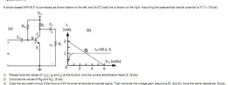
A silicon-based NPN BJT is connected as shown below on the left, and its DC load line is shown on the right. Assuming the base-emitter barrier potential is 0.7V (15 pts) V. w RE (a) w Ic (mA) 1 ) (b) Cat B 2 + V RE E Q 18=20 u A vi 1 Vc (volts) 0 2 4 6 1) Please have the values of Vcc Is and Ic at the point, and the current amplification factor B. (5 pts) 2) Compute the values of Rg and Rc (5 pts) 3) Draw the equivalent circuit if the input is a 50 Hz small amplitude sinusoidal signal. Then compute the voltage gain, assuming R and Rc have the same resistance. (5 pts)