Page 1 of 1
Figure Q6(a) shows a room of 5.0 5.0 x 3.5 m. The front side is an external wall. The interior surface temperature of th
Posted: Tue Apr 26, 2022 7:48 pm
by answerhappygod
- Figure Q6 A Shows A Room Of 5 0 5 0 X 3 5 M The Front Side Is An External Wall The Interior Surface Temperature Of Th 1 (67.46 KiB) Viewed 20 times
- Figure Q6 A Shows A Room Of 5 0 5 0 X 3 5 M The Front Side Is An External Wall The Interior Surface Temperature Of Th 2 (69.52 KiB) Viewed 20 times
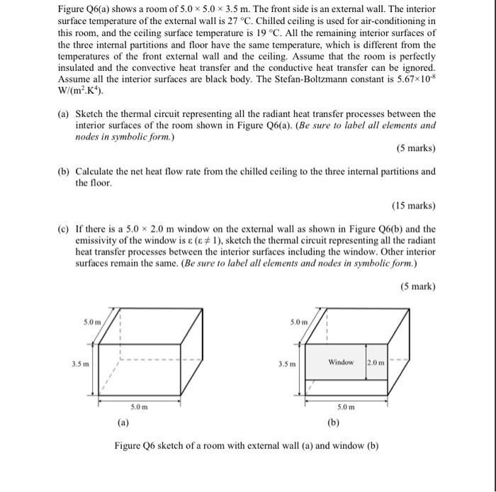
Figure Q6(a) shows a room of 5.0 5.0 x 3.5 m. The front side is an external wall. The interior surface temperature of the external wall is 27 °C. Chilled ceiling is used for air-conditioning in this room, and the ceiling surface temperature is 19°C. All the remaining interior surfaces of the three internal partitions and floor have the same temperature, which is different from the temperatures of the front external wall and the ceiling. Assume that the room is perfectly insulated and the convective heat transfer and the conductive heat transfer can be ignored. Assume all the interior surfaces are black body. The Stefan-Boltzmann constant is 5.67x10* W/(m²K). (a) Sketch the thermal circuit representing all the radiant heat transfer processes between the interior surfaces of the room shown in Figure Q6(a). (Be sure to label all elements and nodes in symbolic form.) (5 marks) (b) Calculate the net heat flow rate from the chilled ceiling to the three internal partitions and the floor. (15 marks) (c) If there is a 5.0 x 2.0 m window on the external wall as shown in Figure Q6(b) and the emissivity of the window is € (E #1), sketch the thermal circuit representing all the radiant heat transfer processes between the interior surfaces including the window. Other interior surfaces remain the same. (Be sure to label all elements and nodes in symbolic form.) (5 mark) 5.0 m 5.0 m 3.5 m 3.5 m Window 2.0 m 5.Om 5.0 m (a) (b) Figure Q6 sketch of a room with external wall (a) and window (b)
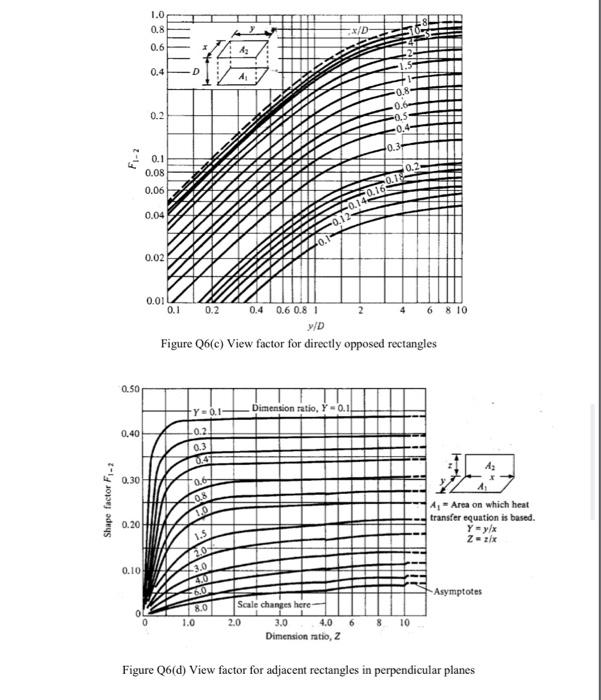
1.0 0.8 X/D 0.6 42 0.4 D A: 0.8- 0.2 0.1 0.08 0.06 0.04 0.02 0.1 0.01 0.2 0.4 0.6 0.81 2 4 6 8 10 W/D Figure Q6(e) View factor for directly opposed rectangles 0.50 +Y-0.1 Dimension ratio, Y -0.1! 0.40 L02 0.3 0.4 0.30 06 Shape factor F1-2 08 1.0 0.20 4.- Area on which heat transfer equation is based Y y/ Zx 1.5 2.0 0.10 3.0 07 6.0 Asymptotes 0 0 8.0 1.0 Scale changes here 2.0 3.0 4.0 6 8 10 Dimension ratio, Z Figure Q6(d) View factor for adjacent rectangles in perpendicular planes