Page 1 of 1
2 Figure (2) shows a tension member comprising a W10 x 45 A572( Fy=50ksi,Fu=65ksi) section connected by 3/4 " bolts (
Posted: Thu Jul 14, 2022 2:56 pm
by answerhappygod
- 2 Figure 2 Shows A Tension Member Comprising A W10 X 45 A572 Fy 50ksi Fu 65ksi Section Connected By 3 4 Bolts 1 (36.22 KiB) Viewed 36 times
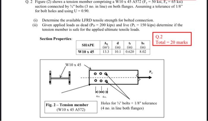
2 Figure (2) shows a tension member comprising a W10 x 45 A572( Fy=50ksi,Fu=65ksi) section connected by 3/4 " bolts ( 3 no. in line) on both flanges. Assuming a tolerance of 1/8. for bolt holes and using U=0.90. (i) Determine the available LFRD tensile strength for bolted connection. (ii) Given applied loads as dead (PDD=200kips) and live (PLL=150kips) determine if the tension member is safe for the applied ultimate tensile loads. Section Properties: Q.2