Page 1 of 1
The diagram below shows a pipe network system. Two connecting reservoirs, 1 and 2 , have water level elevations of 150 f
Posted: Thu Jul 14, 2022 2:54 pm
by answerhappygod
- The Diagram Below Shows A Pipe Network System Two Connecting Reservoirs 1 And 2 Have Water Level Elevations Of 150 F 1 (155.86 KiB) Viewed 43 times
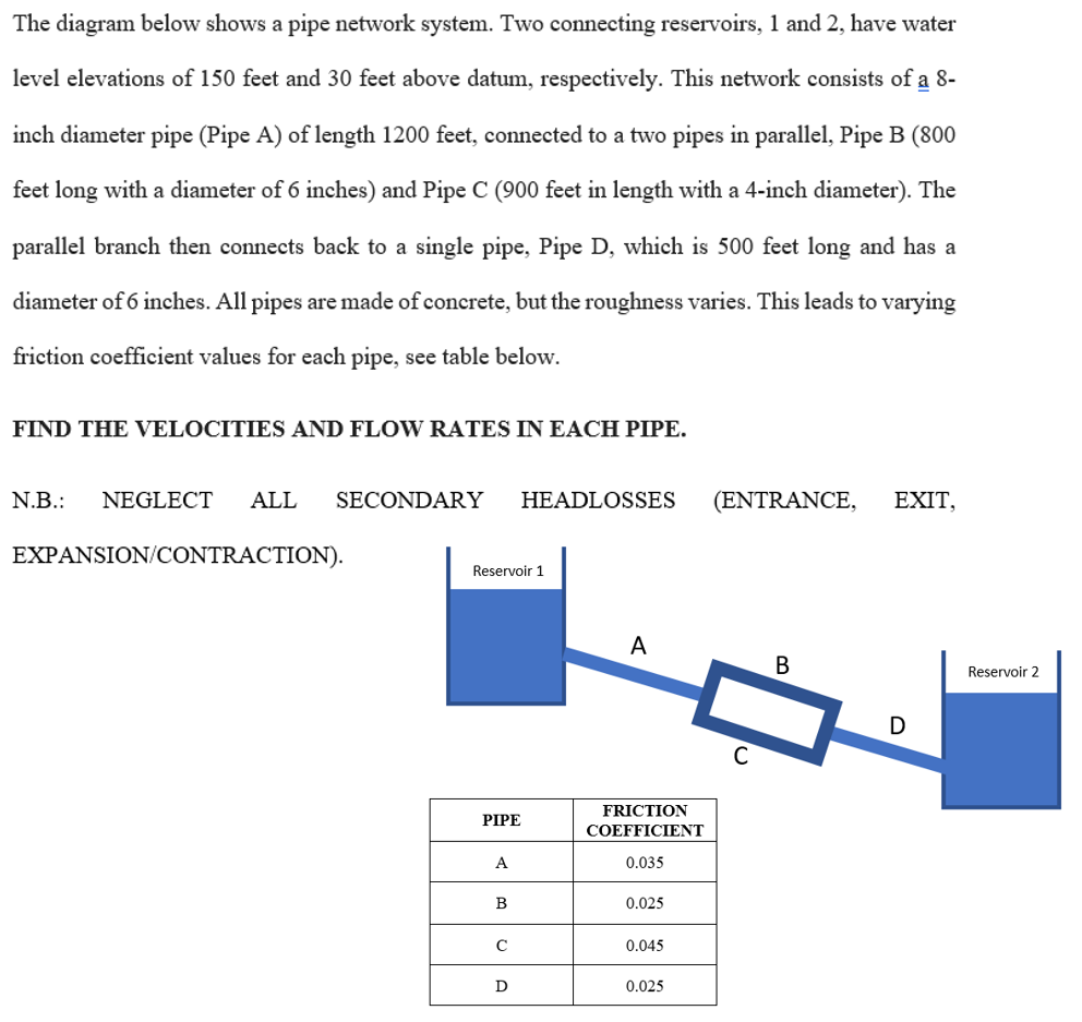
The diagram below shows a pipe network system. Two connecting reservoirs, 1 and 2 , have water level elevations of 150 feet and 30 feet above datum, respectively. This network consists of a 8 inch diameter pipe (Pipe A) of length 1200 feet, connected to a two pipes in parallel, Pipe B (800 feet long with a diameter of 6 inches) and Pipe C ( 900 feet in length with a 4-inch diameter). The parallel branch then connects back to a single pipe, Pipe D, which is 500 feet long and has a diameter of 6 inches. All pipes are made of concrete, but the roughness varies. This leads to varying friction coefficient values for each pipe, see table below. FIND THE VELOCITIES AND FLOW RATES IN EACH PIPE. N.B.: NEGLECT ALL SECONDARY HEADLOSSES (ENTRANCE, EXIT, FXPANSION/CONTR ACTION)