Page 1 of 1
A common-emitter (CE) bipolar junction transistor amplifier is shown in FIGURE 1. FIGURE 1 i. If the amplifier is to ope
Posted: Thu Jul 14, 2022 2:36 pm
by answerhappygod
- A Common Emitter Ce Bipolar Junction Transistor Amplifier Is Shown In Figure 1 Figure 1 I If The Amplifier Is To Ope 1 (97.35 KiB) Viewed 25 times
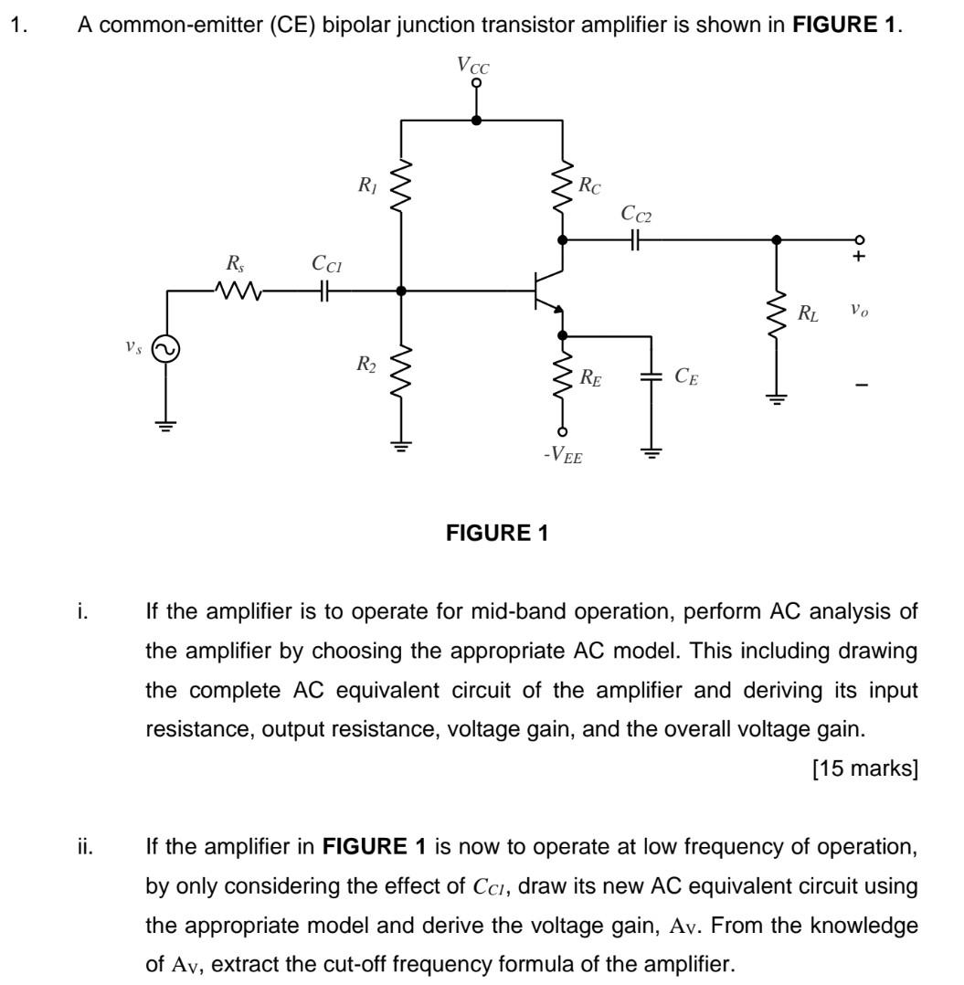
A common-emitter (CE) bipolar junction transistor amplifier is shown in FIGURE 1. FIGURE 1 i. If the amplifier is to operate for mid-band operation, perform AC analysis of the amplifier by choosing the appropriate AC model. This including drawing the complete AC equivalent circuit of the amplifier and deriving its input resistance, output resistance, voltage gain, and the overall voltage gain. [15 marks] ii. If the amplifier in FIGURE 1 is now to operate at low frequency of operation, by only considering the effect of CCl, draw its new AC equivalent circuit using the appropriate model and derive the voltage gain, Av. From the knowledge of Av, extract the cut-off frequency formula of the amplifier.