Page 1 of 1
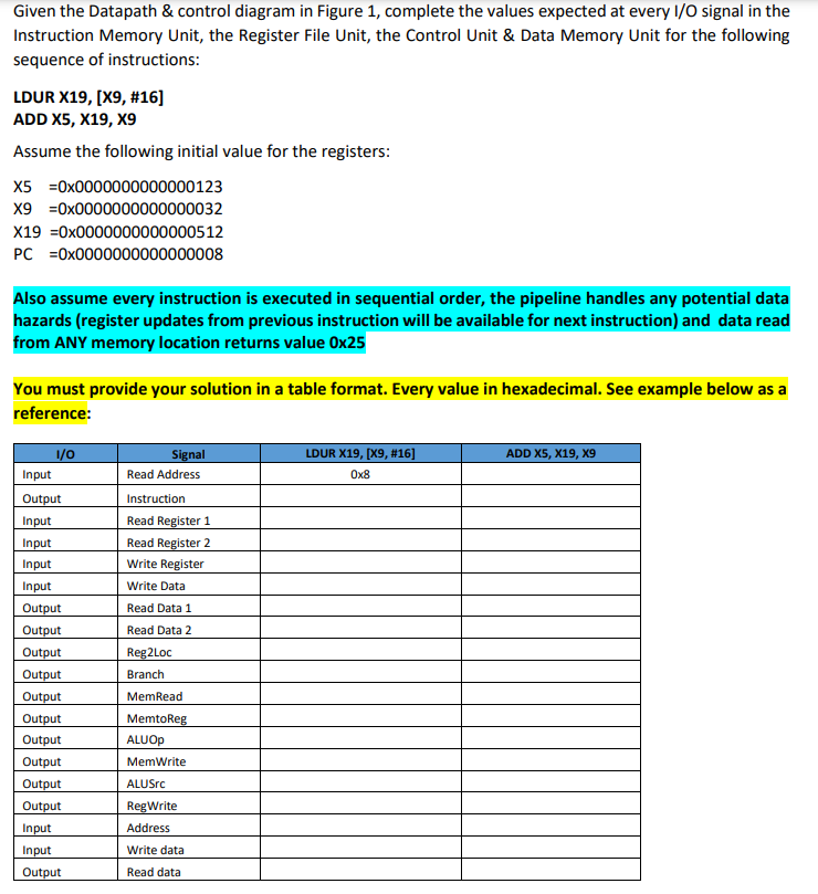
Given the Datapath \& control diagram in Figure 1, complete the values expected at every I/O signal in the Instruction M
Posted: Thu Jul 14, 2022 2:12 pm
by answerhappygod
- Given The Datapath Control Diagram In Figure 1 Complete The Values Expected At Every I O Signal In The Instruction M 1 (114.24 KiB) Viewed 31 times
- Given The Datapath Control Diagram In Figure 1 Complete The Values Expected At Every I O Signal In The Instruction M 2 (60.98 KiB) Viewed 31 times
Given the Datapath \& control diagram in Figure 1, complete the values expected at every I/O signal in the Instruction Memory Unit, the Register File Unit, the Control Unit \& Data Memory Unit for the following sequence of instructions: LDUR X19, [ X9,#16] ADD X5, X19, X9 Assume the following initial value for the registers: X5 =0×0000000000000123x9=0×0000000000000032X19=0×0000000000000512 PC =0×0000000000000008 Also assume every instruction is executed in sequential order, the pipeline handles any potential data hazards (register updates from previous instruction will be available for next instruction) and data read from ANY memory location returns value 0x25 You must provide your solution in a table format. Every value in hexadecimal. See example below as a reference:
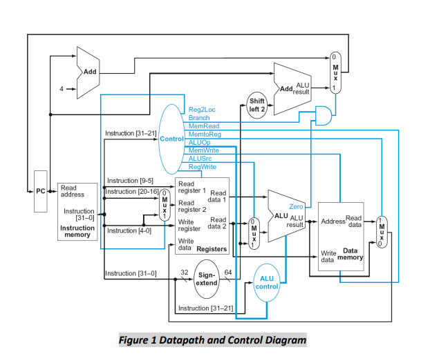
Figure 1 Datapath and Control Diagram