Page 1 of 1
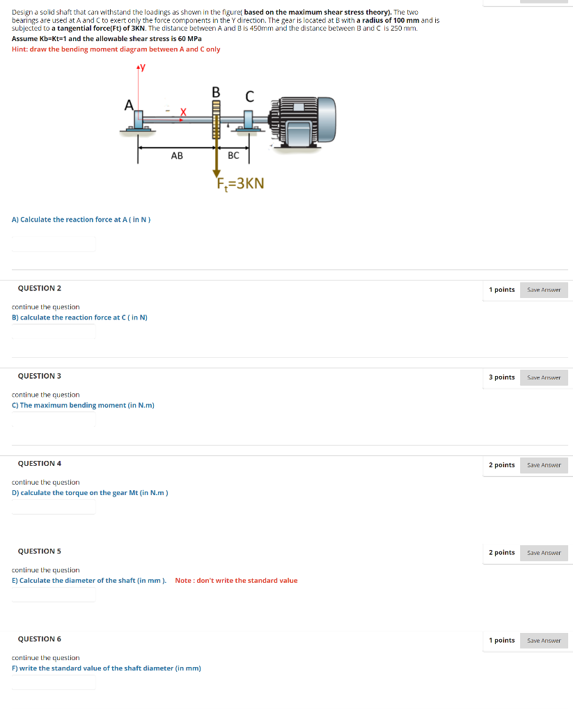
Design a solid shaft that can withstand the loadings as shown in the figureſ based on the maximum shear stress theory).
Posted: Tue Apr 26, 2022 4:58 pm
by answerhappygod
- Design A Solid Shaft That Can Withstand The Loadings As Shown In The Figures Based On The Maximum Shear Stress Theory 1 (101.59 KiB) Viewed 47 times
Design a solid shaft that can withstand the loadings as shown in the figureſ based on the maximum shear stress theory). The two bearings are used at A and C to exert only the force components in the y direction. The gear is located at B with a radius of 100 mm and is subjected to a tangential force(Ft) of 3KN. The distance between A and B is 450mm and the distance between B and C is 250 mm. Assume Kb=Kt=1 and the allowable shear stress is 60 MPa Hint: draw the bending moment diagram between A and Conly TE 90 AB BC F2=3KN A) Calculate the reaction force at A (in N) QUESTION 2 1 points Save Answer continue the question B) calculate the reaction force at C (in N) QUESTION 3 3 points Save Answer continue the question C) The maximum bending moment in N.m) QUESTION 4 2 points Save Answer continue the question D) calculate the torque on the gear Mt (in N.m) QUESTIONS 2 points Save Answer continue the question E) Calculate the diameter of the shaft (in mm). Note: don't write the standard value QUESTION 6 1 points Save Answer continue the question F) write the standard value of the shaft diameter (in mm)