Page 1 of 1
1. DEFINITION A link that is to be investigated in this homework is shown below in Figure 1. The problem is to choose a
Posted: Tue Apr 26, 2022 4:57 pm
by answerhappygod
- 1 Definition A Link That Is To Be Investigated In This Homework Is Shown Below In Figure 1 The Problem Is To Choose A 1 (49.74 KiB) Viewed 43 times
- 1 Definition A Link That Is To Be Investigated In This Homework Is Shown Below In Figure 1 The Problem Is To Choose A 2 (30.84 KiB) Viewed 43 times
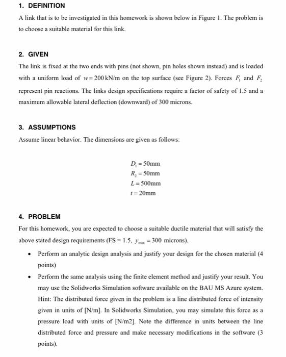
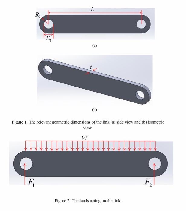
1. DEFINITION A link that is to be investigated in this homework is shown below in Figure 1. The problem is to choose a suitable material for this link. 2. GIVEN The link is fixed at the two ends with pins (not shown, pin holes shown instead) and is loaded with a uniform load of w=200 kN/m on the top surface (see Figure 2). Forces F, and F, represent pin reactions. The links design specifications require a factor of safety of 1.5 and a maximum allowable lateral deflection (downward) of 300 microns. 3. ASSUMPTIONS Assume linear behavior. The dimensions are given as follows: D = 50mm R. = 50mm L = 500mm 1 = 20mm 4. PROBLEM For this homework, you are expected to choose a suitable ductile material that will satisfy the above stated design requirements (FS = 1.5. Y m = 300 microns). • Perform an analytic design analysis and justify your design for the chosen material (4 points) • Perform the same analysis using the finite element method and justify your result. You may use the Solidworks Simulation software available on the BAU MS Azure system. Hint: The distributed force given in the problem is a line distributed force of intensity given in units of [N/m]. In Solidworks Simulation, you may simulate this force as a pressure load with units of [N/m2). Note the difference in units between the line distributed force and pressure and make necessary modifications in the software (3 points)
L R D (a) (b) Figure 1. The relevant geometric dimensions of the link (a) side view and (b) isometric view. W F F2 Figure 2. The loads acting on the link.