Page 1 of 1
The 2-mm thick bar shown below is loaded axially with a fluctuating force, Fmax = 10 kN and Fmin = 0 kN. The load ratio,
Posted: Tue Apr 26, 2022 4:53 pm
by answerhappygod
- The 2 Mm Thick Bar Shown Below Is Loaded Axially With A Fluctuating Force Fmax 10 Kn And Fmin 0 Kn The Load Ratio 1 (493.85 KiB) Viewed 45 times
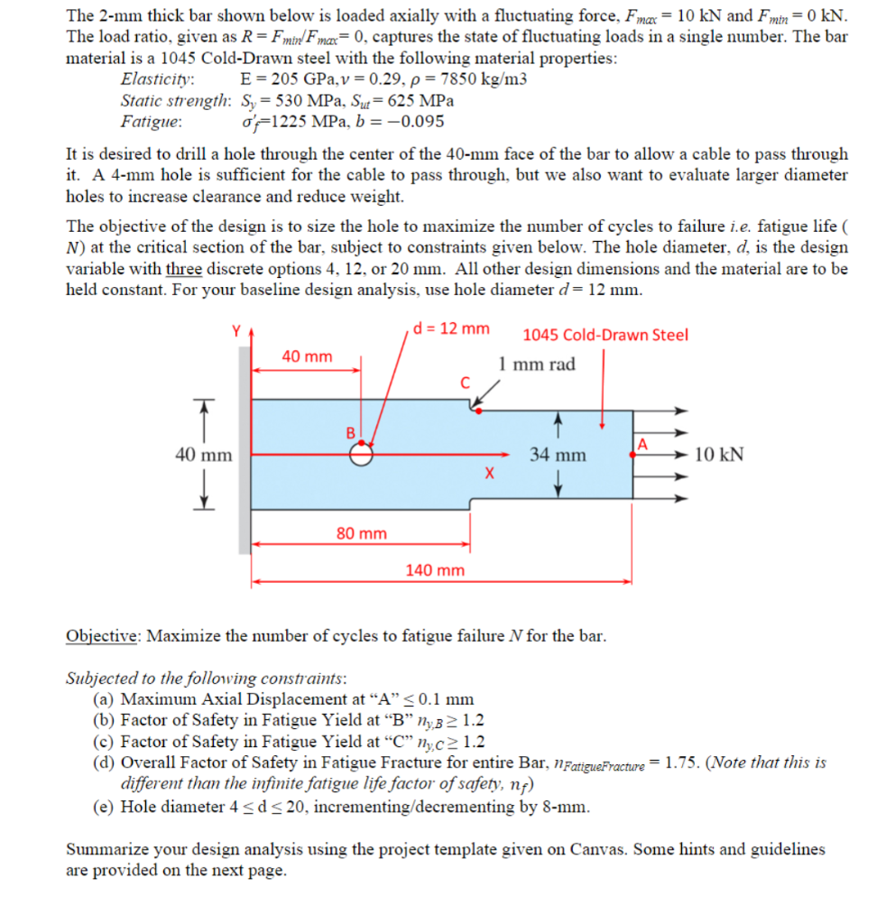
The 2-mm thick bar shown below is loaded axially with a fluctuating force, Fmax = 10 kN and Fmin = 0 kN. The load ratio, given as R = Fmin F mee = 0, captures the state of fluctuating loads in a single number. The bar material is a 1045 Cold-Drawn steel with the following material properties: Elasticity: E = 205 GPa, v = 0.29, p = 7850 kg/m3 Static strength: Sy = 530 MPa, Sut= 625 MPa Fatigue: o'=1225 MPa, b = -0.095 It is desired to drill a hole through the center of the 40-mm face of the bar to allow a cable to pass through it. A 4-mm hole is sufficient for the cable to pass through, but we also want to evaluate larger diameter holes to increase clearance and reduce weight. The objective of the design is to size the hole to maximize the number of cycles to failure i.e. fatigue life ( N) at the critical section of the bar, subject to constraints given below. The hole diameter, d, is the design variable with three discrete options 4, 12, or 20 mm. All other design dimensions and the material are to be held constant. For your baseline design analysis, use hole diameter d= 12 mm. d = 12 mm 40 mm 1045 Cold-Drawn Steel 1 mm rad B |А 40 mm 34 mm 10 kN Х 80 mm 140 mm Objective: Maximize the number of cycles to fatigue failure N for the bar. Subjected to the following constraints: (a) Maximum Axial Displacement at "A" < 0.1 mm (b) Factor of Safety in Fatigue Yield at “B” NyB2 1.2 (c) Factor of Safety in Fatigue Yield at “C”nyc> 1.2 (d) Overall Factor of Safety in Fatigue Fracture for entire Bar, FatigueFracture = 1.75. (Note that this is different than the infinite fatigue life factor of safety, nf) (e) Hole diameter 4 <d<20, incrementing/decrementing by 8-mm. Summarize your design analysis using the project template given on Canvas. Some hints and guidelines are provided on the next page.