Page 1 of 1
The beam shown in the figure below has its left end sliding (guided) and the other end fixed, while the midpoint is pinn
Posted: Tue Apr 26, 2022 4:04 pm
by answerhappygod
- The Beam Shown In The Figure Below Has Its Left End Sliding Guided And The Other End Fixed While The Midpoint Is Pinn 1 (368.33 KiB) Viewed 45 times
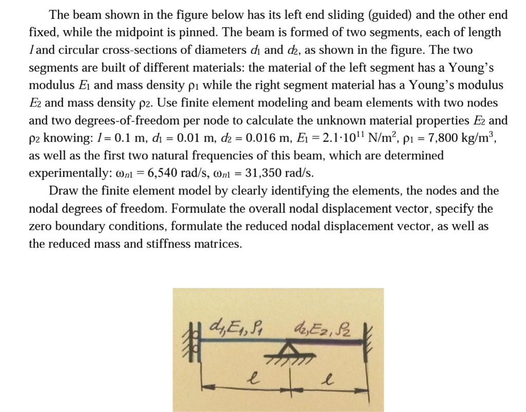
The beam shown in the figure below has its left end sliding (guided) and the other end fixed, while the midpoint is pinned. The beam is formed of two segments, each of length land circular cross-sections of diameters dį and d2, as shown in the figure. The two segments are built of different materials: the material of the left segment has a Young's modulus Ej and mass density pı while the right segment material has a Young's modulus Ez and mass density p2. Use finite element modeling and beam elements with two nodes and two degrees-of-freedom per node to calculate the unknown material properties Ez and p2 knowing: 1= 0.1 m, dı = 0.01 m, dz = 0.016 m, Ei = 2.1.1011 N/m², pı = 7,800 kg/m”, as well as the first two natural frequencies of this beam, which are determined experimentally: On1 = 6,540 rad/s, Oni = 31,350 rad/s. Draw the finite element model by clearly identifying the elements, the nodes and the nodal degrees of freedom. Formulate the overall nodal displacement vector, specify the zero boundary conditions, formulate the reduced nodal displacement vector, as well as the reduced mass and stiffness matrices. d,ES d2, E2,22 pa 019- e l