- Figure 1 Represents An Open Loop Position Control System Using A Dc Motor The Physical System Variables And The Param 1 (266.35 KiB) Viewed 46 times
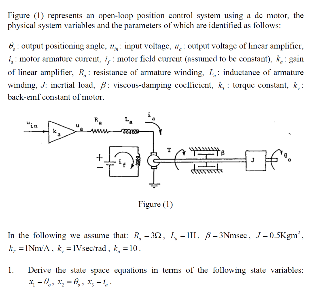
Figure (1) represents an open-loop position control system using a dc motor, the physical system variables and the parameters of which are identified as follows: 0.: output positioning angle, uin : input voltage, u,: output voltage of linear amplifier, in: motor armature current, ij: motor field current (assumed to be constant), kg: gain of linear amplifier, R,: resistance of armature winding, L.: inductance of armature winding, J: inertial load, B: viscous-damping coefficient, kq: torque constant, k, : back-emf constant of motor. La "in u ка www k a 00100 T 8ܐܥܥܥܕ J Figure (1) = In the following we assume that: R. = 392, = 1H, B = 3Nmsec, J = 0.5Kgm”, ky = 1Nm/A, k, = 1Vsec/rad , ka = 10. = = = 2 1. Derive the state space equations in terms of the following state variables: x; = 0., x, = 0,, x= in.