Page 1 of 1
Q3. The fringe pattern shown in Fig. Q2 corresponds to a valve head in contact with the valve seat, under hydrostatic lo
Posted: Tue Apr 26, 2022 3:53 pm
by answerhappygod
- Q3 The Fringe Pattern Shown In Fig Q2 Corresponds To A Valve Head In Contact With The Valve Seat Under Hydrostatic Lo 1 (65.58 KiB) Viewed 26 times
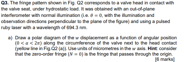
Q3. The fringe pattern shown in Fig. Q2 corresponds to a valve head in contact with the valve seat, under hydrostatic load. It was obtained with an out-of-plane interferometer with normal illumination (i.e. 0 = 0, with the illumination and observation directions perpendicular to the plane of the figure) and using a pulsed ruby laser with a wavelength of 694.3 nm. a) Draw a polar diagram of the w displacement as a function of angular position (0 <a <21) along the circumference of the valve next to the head contact (yellow line in Fig. Q2 (a)). Use units of micrometres in the w axis. Hint: consider that the zero-order fringe (N = 0) is the fringe that passes through the origin. [6 marks]