Page 1 of 1
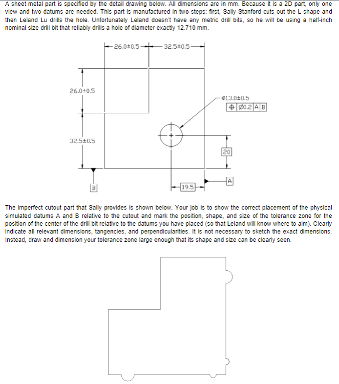
A sheet metal part is specified by the detail drawing below. All dimensions are in mm. Because it is a 2D part, only one
Posted: Tue Apr 26, 2022 3:29 pm
by answerhappygod
- A Sheet Metal Part Is Specified By The Detail Drawing Below All Dimensions Are In Mm Because It Is A 2d Part Only One 1 (92.06 KiB) Viewed 34 times
A sheet metal part is specified by the detail drawing below. All dimensions are in mm. Because it is a 2D part, only one view and two datums are needed. This part is manufactured in two steps: first, Sally Stanford cuts out the shape and then Leland Lu drills the hole. Unfortunately Leland doesn't have any metric drill bits, so he will be using a half-inch nominal size drill bit that reliably drills a hole of diameter exactly 12.710 mm. -26.0-0.5 -32.5+0.5 26.010.5 - $13.010.5 00.2 AB 1 32.520.5 20 19.5 The imperfect cutout part that Sally provides is shown below. Your job is to show the correct placement of the physical simulated datums A and B relative to the cutout and mark the position, shape, and size of the tolerance zone for the position of the center of the drill bit relative to the datums you have placed (so that Leland will know where to aim). Clearly indicate all relevant dimensions, tangencies, and perpendicularities. It is not necessary to sketch the exact dimensions. Instead, draw and dimension your tolerance zone large enough that its shape and size can be clearly seen.