Page 1 of 1
1) Fourier Transforms and Electrical Circuits: RF M Vin(t) 1, R mini Vout + Lout Rout a) Consider the following circuit,
Posted: Tue Apr 26, 2022 3:23 pm
by answerhappygod
- 1 Fourier Transforms And Electrical Circuits Rf M Vin T 1 R Mini Vout Lout Rout A Consider The Following Circuit 1 (38.27 KiB) Viewed 37 times
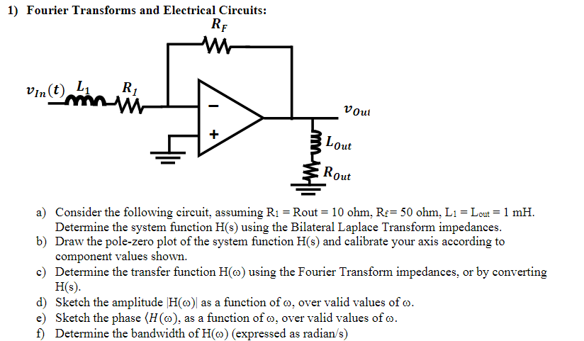
1) Fourier Transforms and Electrical Circuits: RF M Vin(t) 1, R mini Vout + Lout Rout a) Consider the following circuit, assuming R1 = Rout = 10 ohm. Re= 50 ohm. L1 = Lout = 1 mH. Determine the system function H(s) using the Bilateral Laplace Transform impedances. b) Draw the pole-zero plot of the system function H(s) and calibrate your axis according to component values shown. c) Determine the transfer function Hw) using the Fourier Transform impedances, or by converting HS). d) Sketch the amplitude H@) as a function of o, over valid values of o. e) Sketch the phase (HQ), as a function of o, over valid values of 6. f) Determine the bandwidth of Ho) (expressed as radian/s)