Page 1 of 1
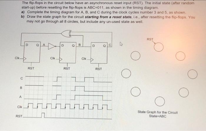
The flip-flops in the circuit below have an asynchronous reset input (RST). The initial state (after random start-up) be
Posted: Tue Apr 26, 2022 3:15 pm
by answerhappygod

- The Flip Flops In The Circuit Below Have An Asynchronous Reset Input Rst The Initial State After Random Start Up Be 1 (42.48 KiB) Viewed 19 times
- The Flip Flops In The Circuit Below Have An Asynchronous Reset Input Rst The Initial State After Random Start Up Be 2 (42.48 KiB) Viewed 19 times
The flip-flops in the circuit below have an asynchronous reset input (RST). The initial state (after random start-up) before resetting the flip-flops is ABC=011, as shown in the timing diagram. a) Complete the timing diagram for A, B, and C during the clock cycles number 3 and 5, as shown b) Draw the state graph for the circuit starting from a reset state, i.e. after resetting the flip-flops. You may not go through all 8 circles, but include any un-used state as well RST D D D Q B D 0 c Clk 1 CIK Cik RST RST RST O С B A A Clk State Graph for the Circuit State=ABC RST