Page 1 of 1
For the circuit shown with the output voltage defined on the capacitor C2: R1 1 ΚΩ x(t) ci HH 500 uF C2 500 uF y(t) Y(s)
Posted: Tue Apr 26, 2022 3:01 pm
by answerhappygod
- 1 (62.02 KiB) Viewed 21 times
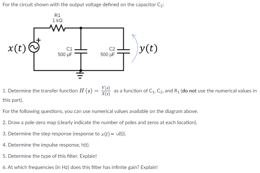
For the circuit shown with the output voltage defined on the capacitor C2: R1 1 ΚΩ x(t) ci HH 500 uF C2 500 uF y(t) Y(s) 1. Determine the transfer function H (s) = X(8) as a function of C1, C2, and R1 (do not use the numerical values in this part). For the following questions, you can use numerical values available on the diagram above. 2. Draw a pole-zero map (clearly indicate the number of poles and zeros at each location). 3. Determine the step response (response to x(t) = u(t)). 4. Determine the impulse response, h(t). 5. Determine the type of this filter. Explain! 6. At which frequencies (in Hz) does this filter has infinite gain? Explain!