Page 1 of 1
The objective of the liquid blending system shown in Fig. 1 is to make product which meets the sales specification on th
Posted: Tue Apr 26, 2022 2:16 pm
by answerhappygod
- The Objective Of The Liquid Blending System Shown In Fig 1 Is To Make Product Which Meets The Sales Specification On Th 1 (120.54 KiB) Viewed 24 times
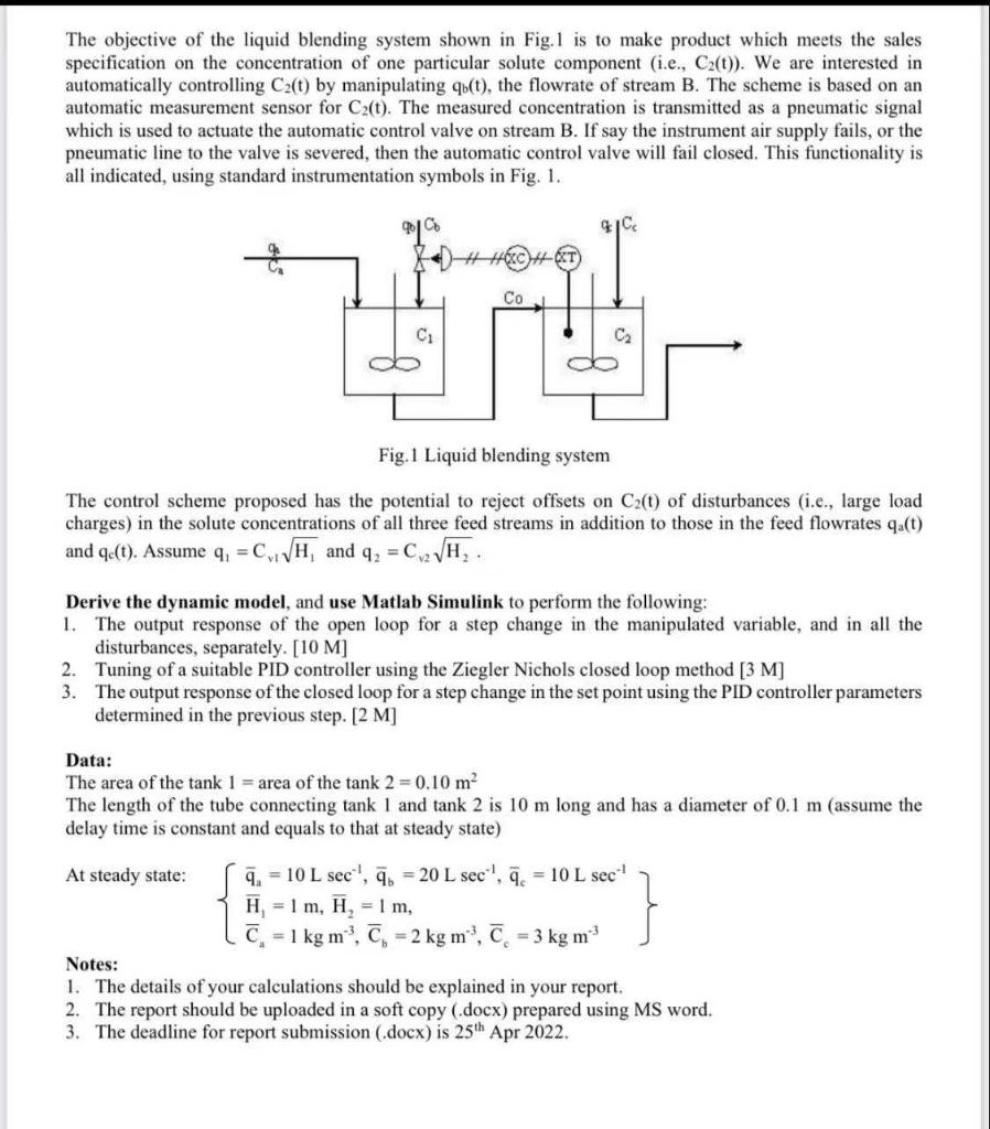
The objective of the liquid blending system shown in Fig. 1 is to make product which meets the sales specification on the concentration of one particular solute component (i.e., Cz(t)). We are interested in automatically controlling Cz(t) by manipulating qu(t), the flowrate of stream B. The scheme is based on an automatic measurement sensor for Cz(t). The measured concentration is transmitted as a pneumatic signal which is used to actuate the automatic control valve on stream B. If say the instrument air supply fails, or the pneumatic line to the valve is severed, then the automatic control valve will fail closed. This functionality is all indicated, using standard instrumentation symbols in Fig. 1. 91C HT Co C C2 oo Fig. 1 Liquid blending system The control scheme proposed has the potential to reject offsets on Cz(t) of disturbances (i.e., large load charges) in the solute concentrations of all three feed streams in addition to those in the feed flowrates qu(t) and e(t). Assume 4, = C:\H, and q2 = C2V H, Derive the dynamic model, and use Matlab Simulink to perform the following: 1. The output response of the open loop for a step change in the manipulated variable, and in all the disturbances, separately. [10 M) 2. Tuning of a suitable PID controller using the Ziegler Nichols closed loop method [3 M] 3. The output response of the closed loop for a step change in the set point using the PID controller parameters determined in the previous step. [2 M] Data: The area of the tank 1 = area of the tank 2=0.10 m The length of the tube connecting tank 1 and tank 2 is 10 m long and has a diameter of 0.1 m (assume the delay time is constant and equals to that at steady state) At steady state: 7. = 10 L sec', 7. = 20 L sec, 7. = 10 L sec! H = 1 m, H = 1 m, c. = 1 kg mº, C = 2 kg mº, C = 3 kg m } 1. The details of your calculations should be explained in your report. 2. The report should be uploaded in a soft copy (.docx) prepared using MS word. 3. The deadline for report submission (.docx) is 25th Apr 2022.