Page 1 of 1
QUESTION FOUR a A. Explain the iterative methods used in power flow analysis. [3] B. The Figure 4 below shows the one-li
Posted: Tue Apr 26, 2022 2:15 pm
by answerhappygod
- Question Four A A Explain The Iterative Methods Used In Power Flow Analysis 3 B The Figure 4 Below Shows The One Li 1 (180.74 KiB) Viewed 22 times
- Question Four A A Explain The Iterative Methods Used In Power Flow Analysis 3 B The Figure 4 Below Shows The One Li 2 (131.55 KiB) Viewed 22 times
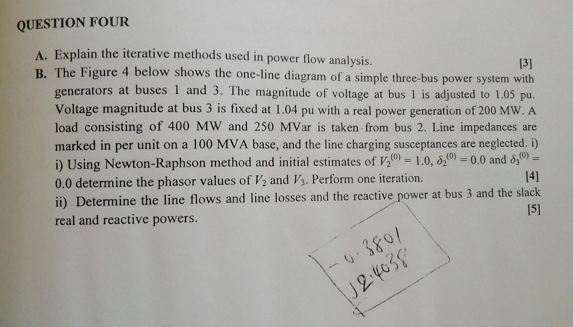
QUESTION FOUR a A. Explain the iterative methods used in power flow analysis. [3] B. The Figure 4 below shows the one-line diagram of a simple three-bus power system with generators at buses 1 and 3. The magnitude of voltage at bus 1 is adjusted to 1.05 pu. Voltage magnitude at bus 3 is fixed at 1.04 pu with a real power generation of 200 MW. A load consisting of 400 MW and 250 MVar is taken from bus 2. Line impedances are marked in per unit on a 100 MVA base, and the line charging susceptances are neglected. i) i) Using Newton-Raphson method and initial estimates of V20) = 1.0, 82%) = 0.0 and 83(0) = [4] 0.0 determine the phasor values of V2 and V3. Perform one iteration. ii) Determine the line flows and line losses and the reactive power at bus 3 and the slack [5] real and reactive powers. = 0.3801 12:4038
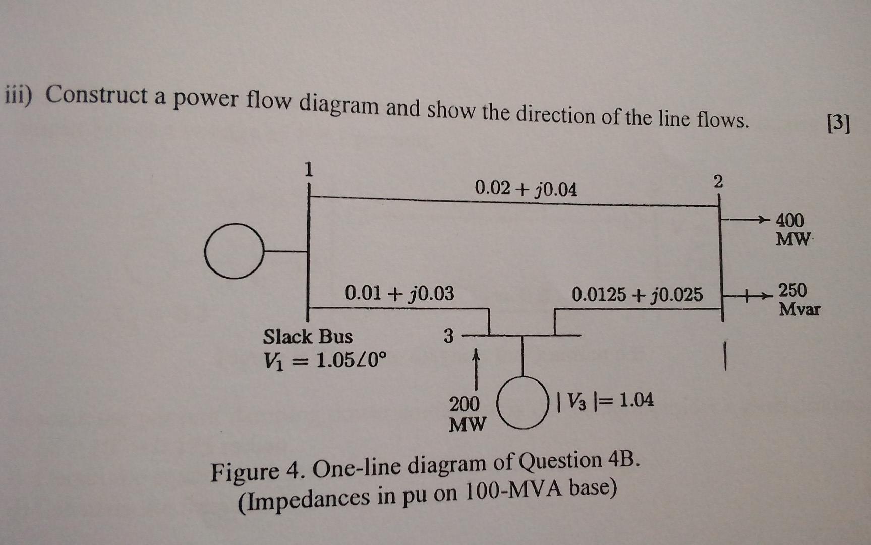
iii) Construct a power flow diagram and show the direction of the line flows. [3] 1 0.02 + 30.04 2 400 MW 0.01 + 30.03 0.0125 + 0.025 250 Mvar 3 Slack Bus Vi = 1.0520° 1 200 MW O 16 1= 1.04 C = Figure 4. One-line diagram of Question 4B. (Impedances in pu on 100-MVA base)