Page 1 of 1
3) Using branch current analysis looking into Node B to calculate the currents in each branch. Use KCL to verify the cur
Posted: Tue Apr 26, 2022 2:03 pm
by answerhappygod
- 3 Using Branch Current Analysis Looking Into Node B To Calculate The Currents In Each Branch Use Kcl To Verify The Cur 1 (70.75 KiB) Viewed 50 times
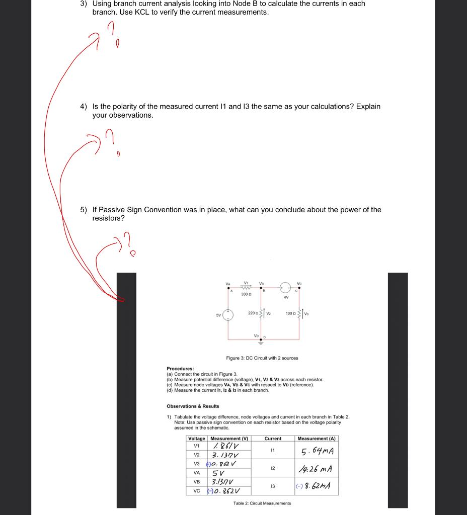
3) Using branch current analysis looking into Node B to calculate the currents in each branch. Use KCL to verify the current measurements. 1 e 4) Is the polarity of the measured current 11 and 13 the same as your calculations? Explain your observations. 5) If Passive Sign Convention was in place, what can you conclude about the power of the resistors? Vi Ve 330 4V 2200 IV SV 1000 SV Vo Figure 3: DC Circuit with 2 sources Procedures: (a) Connect the circuit in Figure 3. (b) Measure potential difference (voltage), V1, V2 & V3 across each resistor c) Measure node voltages VA, V8 & Vc with respect to VD (reference), (d) Measure the current 11, 12 & 13 in each branch. Observations & Results 1) Tabulate the voltage difference, node voltages and current in each branch in Table 2. Note: Use passive sign convention on each resistor based on the voltage polarity assumed in the schematic Current Measurement (A) 11 5.64MA Voltage Measurement (V) V1 1861V V2 3.1371 v3 40.8.2V VA 5V VB 3./37 V VC -) 0.862V 12 14.26 mA 13 | (-) 8. 62MA Table 2: Circuit Measurements