Page 1 of 1
Consider the simply supported beam shown below which is subjected to the specified (unfactored) loads shown in in Fig. 3
Posted: Tue Apr 26, 2022 1:23 pm
by answerhappygod
- Consider The Simply Supported Beam Shown Below Which Is Subjected To The Specified Unfactored Loads Shown In In Fig 3 1 (118.35 KiB) Viewed 33 times
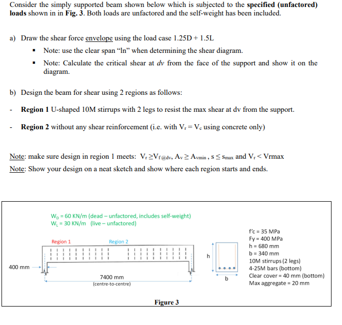
Consider the simply supported beam shown below which is subjected to the specified (unfactored) loads shown in in Fig. 3. Both loads are unfactored and the self-weight has been included. a) Draw the shear force envelope using the load case 1.25D + 1.5L · Note: use the clear span “In” when determining the shear diagram. Note: Calculate the critical shear at dy from the face of the support and show it on the diagram b) Design the beam for shear using 2 regions as follows: Region 1 U-shaped 10M stirrups with 2 legs to resist the max shear at dy from the support. Region 2 without any shear reinforcement (i.e. with V, =Vc using concrete only) Note: make sure design in region 1 meets: V.Vr@dv, Ay Aymin , s<Smax and V, < Vrmax Note: Show your design on a neat sketch and show where each region starts and ends. W. = 60 KN/m (dead - unfactored, includes self-weight) W = 30 KN/m (live - unfactored) Region 1 Region 2 1 h f'c = 35 MPa Fy = 400 MPa h = 680 mm b = 340 mm 10M stirrups (2 legs) 4-25M bars (bottom) Clear cover = 40 mm (bottom) Max aggregate = 20 mm 400 mm 7400 mm (centre-to-centre) b Figure 3