Page 1 of 1
The RC circuit shown in this diagram consists of a battery Emf, a resistor R, and a capacitor C . When the switch is ope
Posted: Tue Jul 12, 2022 1:39 pm
by answerhappygod
- The Rc Circuit Shown In This Diagram Consists Of A Battery Emf A Resistor R And A Capacitor C When The Switch Is Ope 1 (167.34 KiB) Viewed 28 times
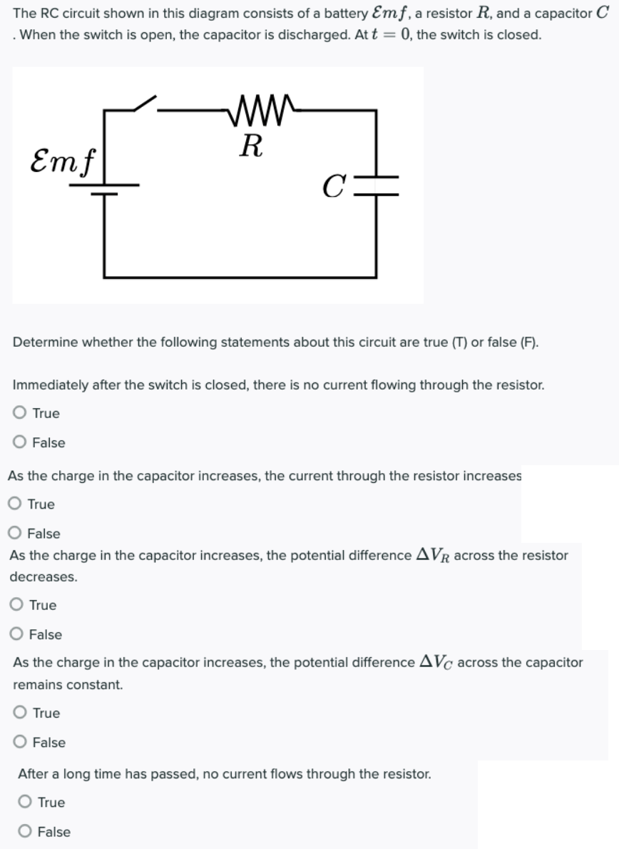
The RC circuit shown in this diagram consists of a battery Emf, a resistor R, and a capacitor C . When the switch is open, the capacitor is discharged. At t = 0, the switch is closed. Emf R с Determine whether the following statements about this circuit are true (T) or false (F). Immediately after the switch is closed, there is no current flowing through the resistor. O True O False As the charge in the capacitor increases, the current through the resistor increases O True O False As the charge in the capacitor increases, the potential difference AVR across the resistor decreases. True False As the charge in the capacitor increases, the potential difference AVC across the capacitor remains constant. O True O False After a long time has passed, no current flows through the resistor. O True O False